
Motion control systems

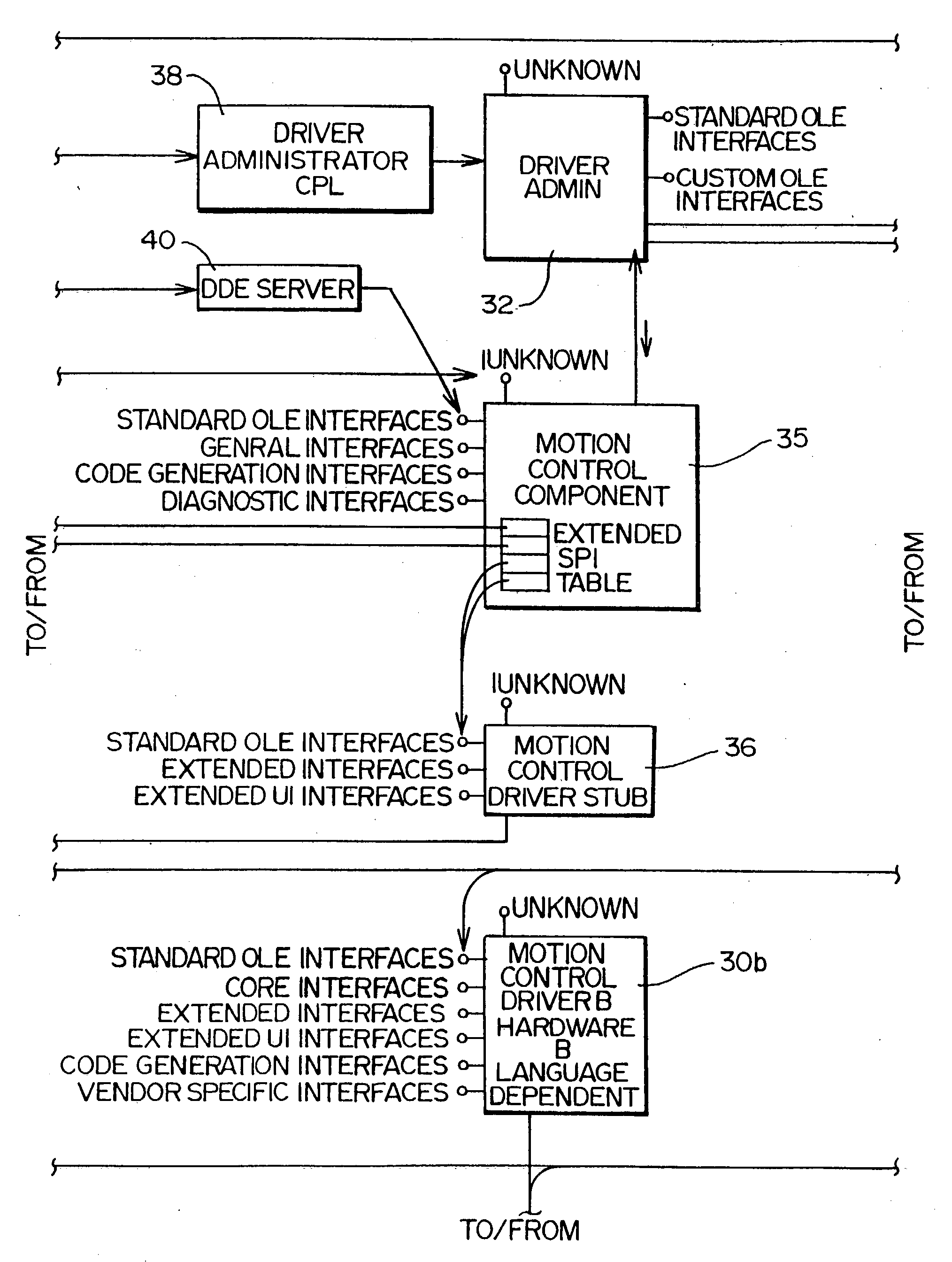
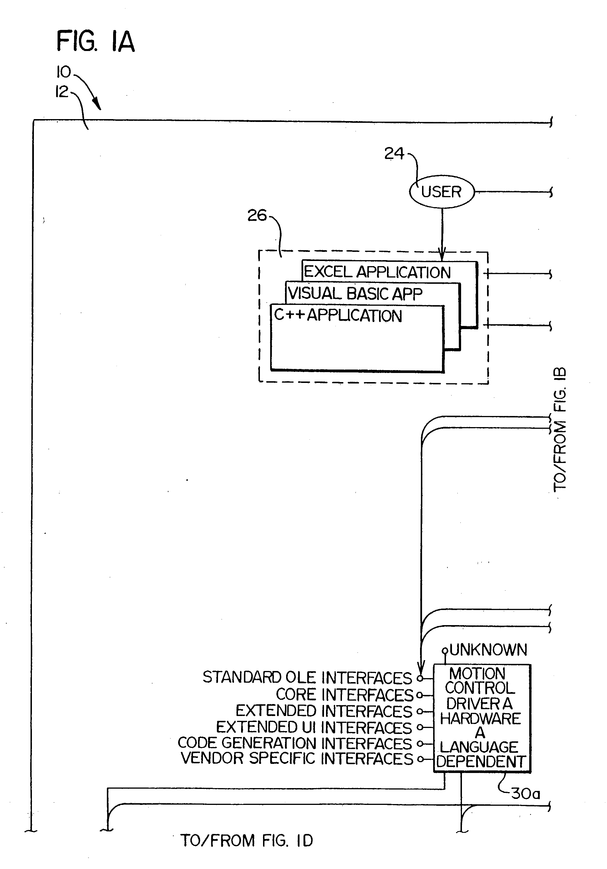
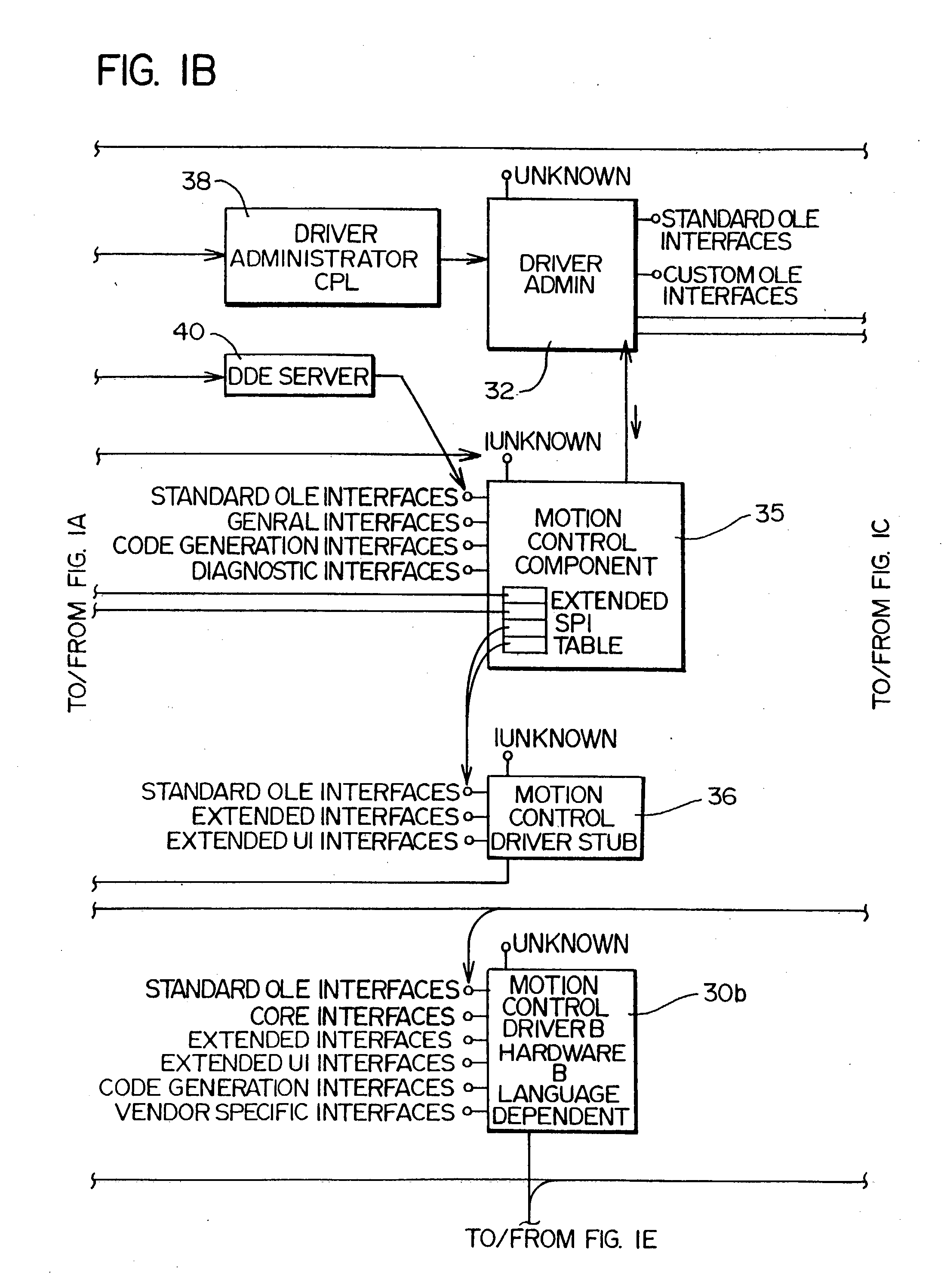
a technology of motion control and control commands, applied in the field of motion control systems, can solve the problems of not providing the application programmer with the ability to control the hardware in base incremental steps, and the software driver model currently used for printers and the like is not applicable to the development of a sequence of control commands for motion control devices

Inactive Publication Date: 2008-11-06
ROY G BIV CORP
View PDF99 Cites 15 Cited by
  • Summary
  • Abstract
  • Description
  • Claims
  • Application Information

AI Technical Summary

Benefits of technology

[0026](c) can easily be extended to support additional hardware configurations; and
[0030]The use of component functions that are separate from driver functions isolates the programmer from the complexities of programming to a specific motion control device. This arrangement also allows a given application program to be used without modification for any motion control device having a software driver associated therewith.

Problems solved by technology

While this approach does isolates the application programmer from the complexities of programming to each hardware configuration in existence, this approach does not provide the application programmer with the ability to control the hardware in base incremental steps.
The software driver model currently used for printers and the like is thus not applicable to the development of a sequence of control commands for motion control devices.

Method used


Image

  • Motion control systems
  • Motion control systems
  • Motion control systems

Examples


example 1

[0333]The first example illustrates how the language driver 44 might deal with the Driver function IXMC_DrvExt_Test::Move.

Cmd Format: D%d,+:@[snd]GO%b+:@[snd]

Rsp Format: @[crlf]>@[rcv]@[crlf]>@[rcv]

Driver function Call: pXMCDrvExtTest->Move(20.0, 30.0)

[0334]This function call directs the motion control device to move 20 units in the x direction and 30 units in the y direction.

The driver communicates with the stream as follows:

[0335]Step 1. Perform the operation in the command format template up to the first @ symbol. This builds a raw command string of “D20.0,30.0:”

[0336]Step 2. After the first @ symbol is the send command, which sends the string that was built in step 1. The language driver has now reached the G in the command format template.

[0337]Step 3. After the send command, the language driver reads a response from the stream to confirm that the command string was received and processed correctly. The response string received from the stream is as follows: “\r\n>”.

[0338]Step ...

example 2

[0342]The second example illustrates how the language driver 44 might deal with the Driver function IXMC_DrvExt_Test::SetVelocity.

Cmd Format: V%lf,+:@[snd]

Rsp Format: @[crlf]>@[rcv]

Driver function Call: pXMCDrvExtTest->SetVelocity(NOP, 22.0)

Explanation Set the velocity of the y axis to 22.0.

Raw Command String: “V,22.0:”

[0343]Raw Response String: “\r\n>” (expected)

example 3

[0344]The third example illustrates how the language driver 44 might deal with the Driver function

IXMC_DrvExt_Test::GetVelocity.

[0345]Cmd Format: GV%b+:@[snd]

Rsp Format: %d,+@[crlf]>@[rcv]

Driver function Call: pXMCDrvExtTest->GetVelocity(NOP, &dfY_Vel)

Explanation Get the velocity set for the y axis.

Raw Command String: “GV01:”

[0346]Raw Response String: “,44.0\r\n>” (expected)

dfY_Vel=44.0


PUM


Abstract

A system for motion control in which an application is developed that is independent from the actual motion control hardware used to implement the system. The system comprises a software system that employs an application programming interface comprising component functions and a service provider interface comprising driver functions. A system programmer writes an application that calls the component functions. Code associated with the component functions relates these functions to the driver functions. A hardware designer writes driver code that implements the driver functions on a given motion control hardware product. The driver functions are separated into core and extended driver functions. All software drivers implement the core driver functions, while the software drivers need not contain code for implementing the extended driver functions. If the software driver does not contain code to implement an extended driver function, the functionality of the extended driver function is obtained through a combination of core driver functions. The system programmer may also select one or more streams that allow the control commands to be communicated to, and response data to be communicated from, motion control hardware.

Description

RELATED APPLICATIONS[0001]This is a continuation of U.S. patent application Ser. No. 10 / 021,669 filed on Dec. 10, 2001, which is a continuation of U.S. patent application Ser. No. 09 / 191,981 filed on Nov. 13, 1998, now abandoned, which is a continuation of U.S. patent application Ser. No. 08 / 656,421 filed on May 30, 1996 now U.S. Pat. No. 5,867,385, which is a continuation-in-part of U.S. patent application Ser. No. 08 / 454,736 filed on May 30, 1995 now U.S. Pat. No. 5,691,897.[0002]Priority is also claimed from U.S. patent application Ser. No. 09 / 795,777 filed on Feb. 27, 2001, which is incorporated by reference in its entirety and which is a continuation of U.S. patent application Ser. No. 09 / 205,627 filed on Dec. 3, 1998, now U.S. Pat. No. 6,209,037, which claims benefit of U.S. Provisional Patent Application Ser. No. 60 / 067,466 filed on Dec. 4, 1997, and which is a continuation of U.S. patent application Ser. No. 09 / 191,981 filed on Nov. 13, 1998, now abandoned, which is a contin...

Claims


Application Information

Patent Timeline
Patent Type & Authority Applications(United States)
IPC IPC(8): G06F19/00G05B19/05G05B15/02G05B19/18G05B19/414G05B19/4155G05B19/416G06F9/06G06F9/445
CPCG05B19/19G05B19/416G05B2219/23262G05B2219/23265G05B2219/34208G05B2219/34216G05B2219/34263G05B2219/34287G05B2219/36035G05B2219/36036G05B2219/36037G05B2219/43167Y02P90/02
Inventor BROWN, DAVID W.CLARK, JAY S.
Owner ROY G BIV CORP
Learn More