Method of optimizing a well path during drilling

Active Publication Date: 2008-11-06
SCHLUMBERGER TECH CORP
View PDF18 Cites 83 Cited by
  • Summary
  • Abstract
  • Description
  • Claims
  • Application Information

AI Technical Summary

Benefits of technology

[0011]Exemplary embodiments of the present invention provide several advantages over prior art surveying techniques. For example, in well twinning applications, exemplary embodiments of this invention provide for a substantially real-time determination of a definitive well path for the drilling well

Problems solved by technology

Depending upon the measurement accuracy required, violation of these assumptions can be problematic.
Thus the actual magnetic field may not be known with sufficient accuracy.
On-site measurements of the Earth's field are sometimes also utilized; however, obtaining reliable on-site measurements can be problematic (due to the presence of magnetic interference at the rig site).
Such interference is known to cause errors in the calculated borehole azimuth values.
Magnetic interference is also commonly encounte

Method used


Image

  • Method of optimizing a well path during drilling
  • Method of optimizing a well path during drilling
  • Method of optimizing a well path during drilling

Examples


Example

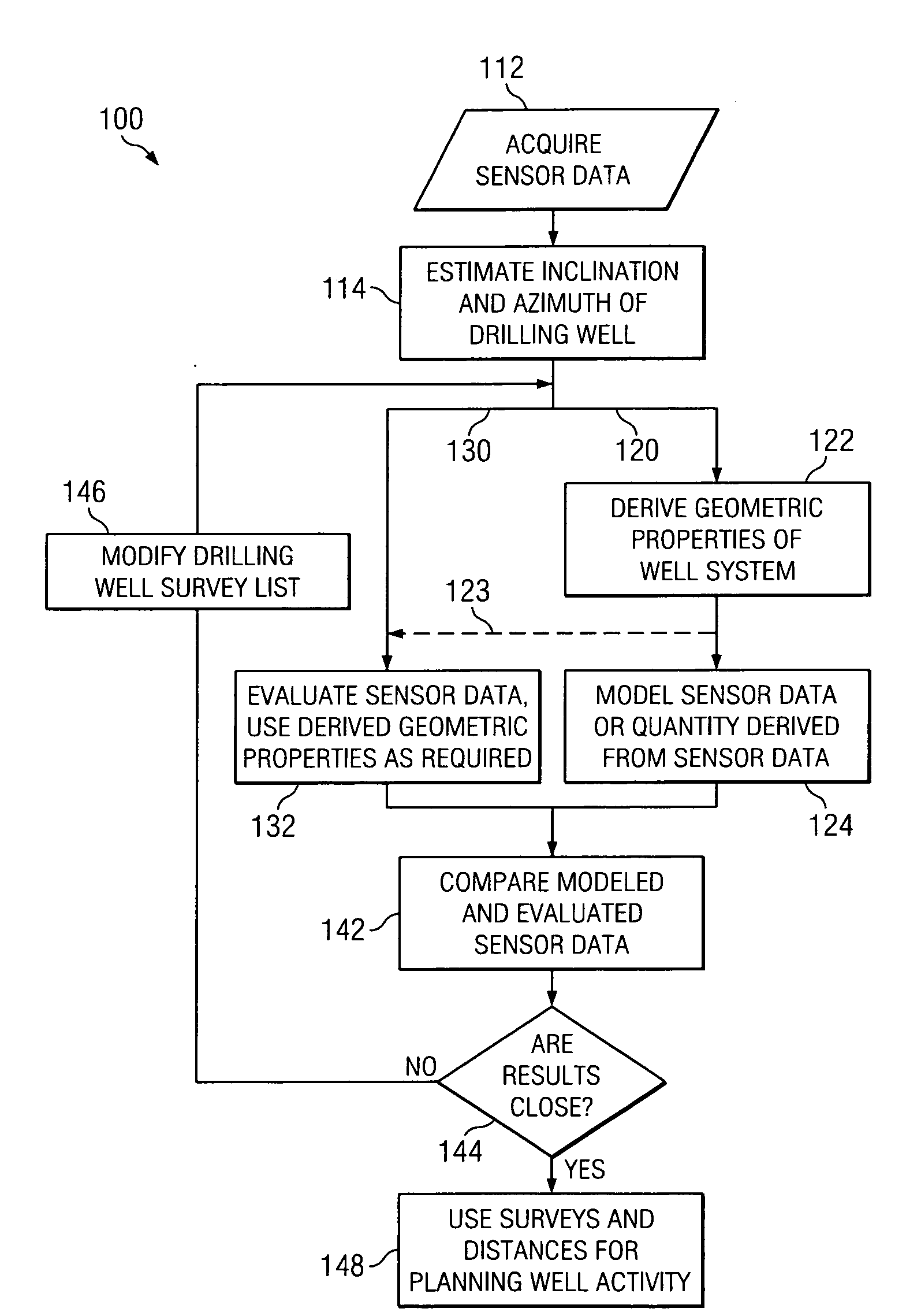
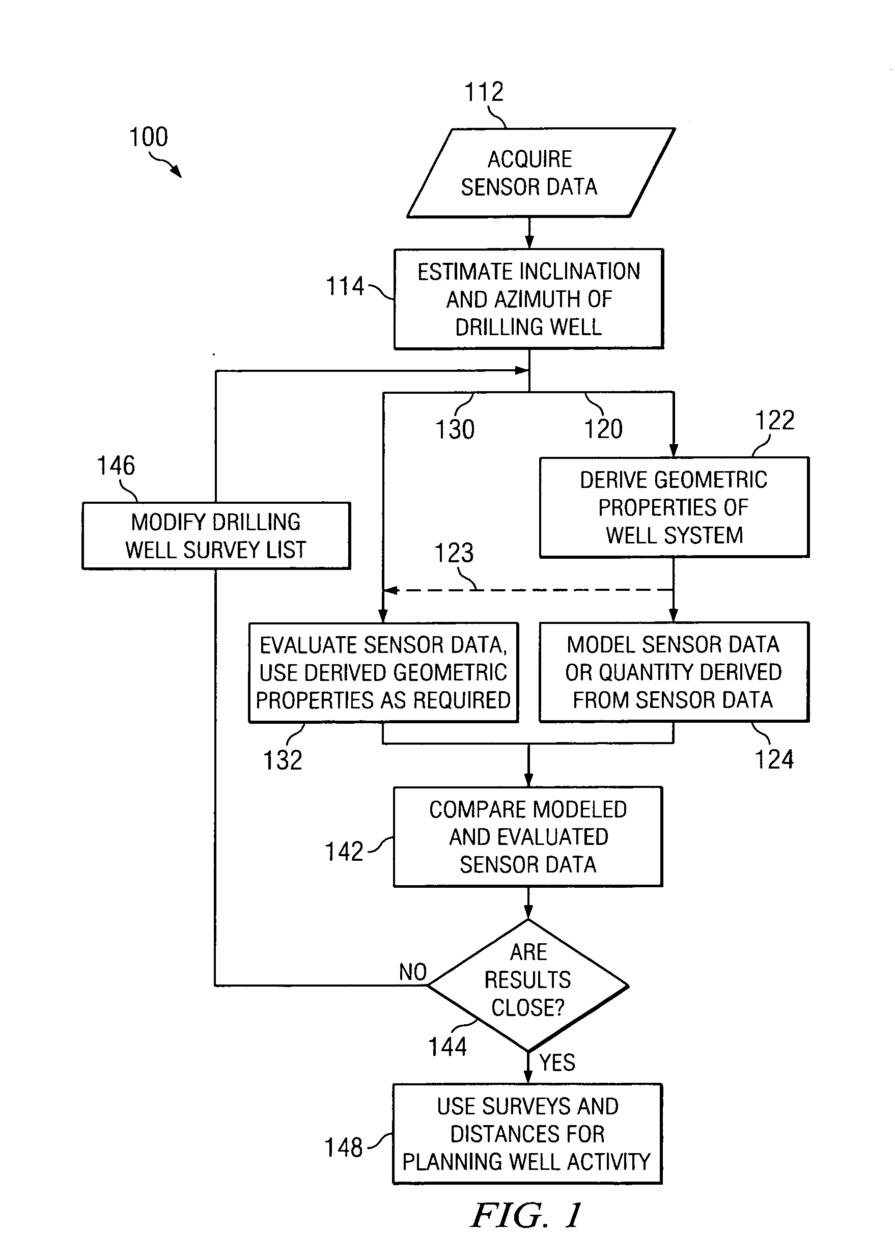
[0022]With reference now to FIG. 1, a general embodiment 100 of the present invention is depicted in flow chart form. As shown, the invention includes acquiring data at 112 and making a preliminary estimate of the inclination and azimuth of a drilling well 114 (e.g., using sensor data acquired at 112). Such data may include conventional sensor data or other information relevant to the well path of the drilling well. Steps 112 and 114 are conventional surveying steps and may include standard deterministic / systemic corrections that take into account, for example, BHA magnetic interference and / or errors in the Earth's magnetic field. Pathfinder Energy Services Mac3® represents one such correction algorithm.

[0023]With continued reference to FIG. 1, at step 122 (in path 120) geometric properties of the well system are derived based upon the inclination and azimuth estimated in step 114 (as well as previous survey points). In one exemplary embodiment, a well path may be computed based upo...


PUM


Abstract

A method for determining a list of survey points for a drilling well includes a feedback loop in which one or more measured parameters are compared with computed or derived parameters. The computed parameters are typically obtained from other/additional measurements. For example, in one exemplary embodiment of the invention, a magnetic least distance vector determined via magnetic ranging is compared with a geometric least distance vector computed from conventional borehole surveying measurements. Estimates of the drilling well azimuth and/or inclination may be adjusted to yield a good agreement between the magnetic and geometric least distance vectors. Exemplary embodiments of the present invention advantageously provide for a substantially real-time determination of a definitive well path for a drilling well as well as a substantially real-time relative placement of the drilling well with respect to a target well.

Description

RELATED APPLICATIONS[0001]This application claims the benefit of U.S. Provisional Application Ser. No. 60 / 927,455 entitled Well Path Optimization Between a Drilling Well and a Magnetized Target Well, filed May 3, 2007.FIELD OF THE INVENTION[0002]The present invention relates generally to drilling and surveying subterranean boreholes such as for use in oil and natural gas exploration. In one exemplary embodiment, this invention relates to a method for determining the well path of a drilling well using magnetic ranging measurements from a magnetized target well.BACKGROUND OF THE INVENTION[0003]In conventional borehole surveying, borehole inclination and azimuth (which, together, essentially define a vector or unit vector tangent to the borehole) are determined at a discrete number of longitudinal points along the borehole (e.g., at an approximately defined measured depth interval). Typically, no assumptions are required about the trajectory of the borehole between the discrete measure...

Claims


Application Information

Patent Timeline
IPC IPC(8): G01V3/38G01V3/00
CPCE21B47/022
Inventor ILLFELDER, HERBERT M. J.
Owner SCHLUMBERGER TECH CORP
Why Eureka
Try Eureka