Distributed power management

a technology of distributed power management and integrated circuits, applied in the field of integrated circuits, can solve the problems of unflexible power control, device intended for a first market sector may not be suitable for a second market sector, and achieve the effect of optimizing the size and efficiency of power resources

Active Publication Date: 2008-11-06
COMPASS HORIZON FUNDING COMPANY
View PDF6 Cites 56 Cited by
  • Summary
  • Abstract
  • Description
  • Claims
  • Application Information

AI Technical Summary

Benefits of technology

[0011]The present invention provides significant advantages over the prior art. First, the power resources can be placed on an integrated circuit without concern for the placement of control function and the number of power resources is not limited by the package dissipation and pinout of the device embedding the control function. Second, the power management is flexible in terms of resource placement, thus allowing seamless movement of power resource from one power chip to another. Third, the optimal sizing and efficiency of power resources is granted by the capability of placing the power resource close to the function to be supplied. Fourth, the PMB architecture using a single power management controller addresses multiple subsystems with isochronous power state transitions for shared power domains.

Problems solved by technology

The number of power resources on the chip is limited by the heat dissipation of the package and the available number of pins.
If additional power is needed, it can be supplied by external power resources, but this will require additional pins on the chips using the external power resources and also separate control, since the control logic on the main power management chip does not control external power resources.
In addition to the problem of the number of power resources that can be housed on a single chip, and the control problems presented by the use of external power resources, the prior art has several drawbacks.
First, the power control is not flexible, and thus a device intended for a first market sector may be unsuitable for use in a second market sector, due to different requirement in supply current and regulated voltages.
Also, the prior art is not acceptable for shared power domains where isochronous power state transitions are needed.

Method used


Image

  • Distributed power management
  • Distributed power management
  • Distributed power management

Examples


Embodiment Construction

[0018]The present invention is best understood in relation to FIGS. 1-5 of the drawings, like numerals being used for like elements of the various drawings.

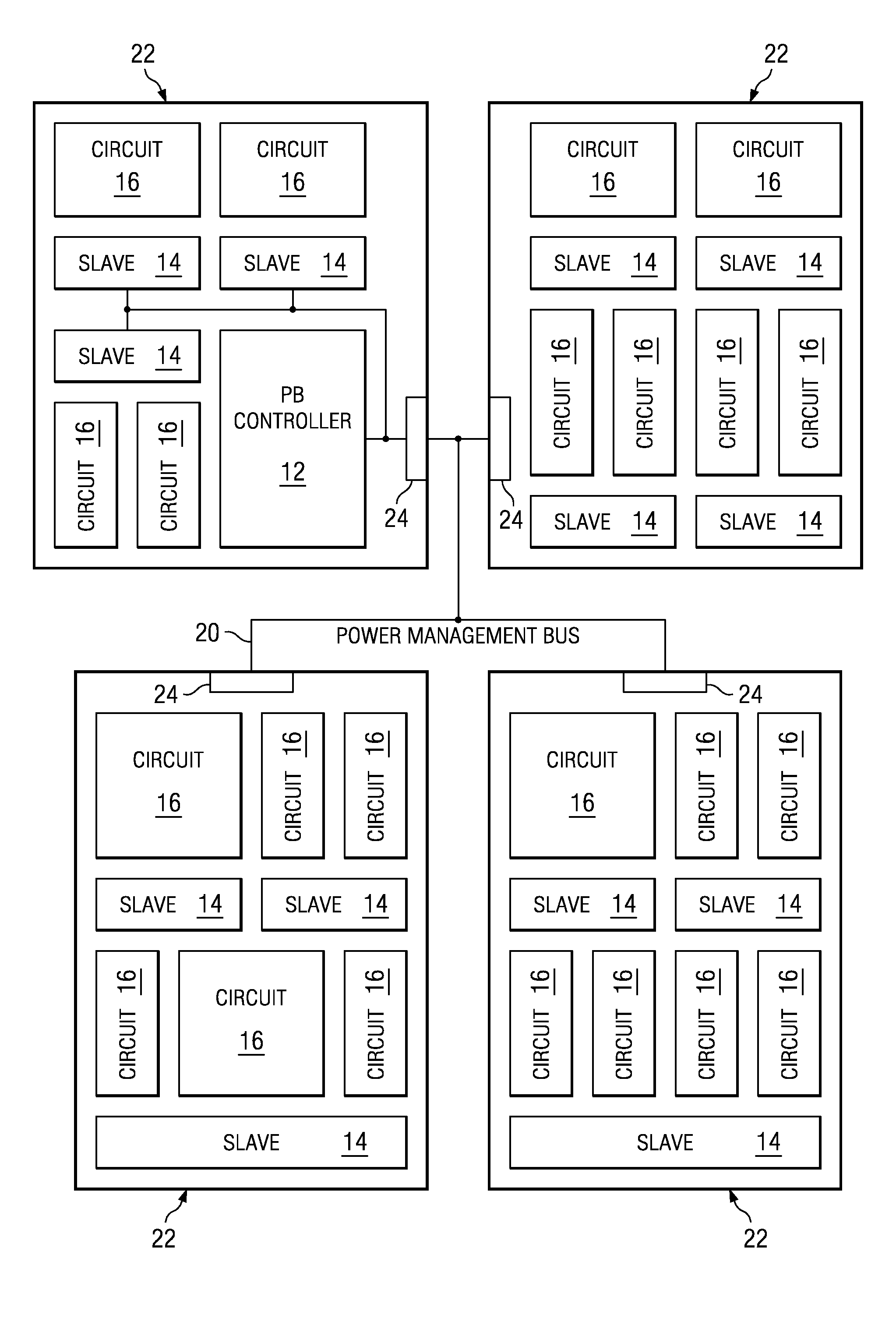
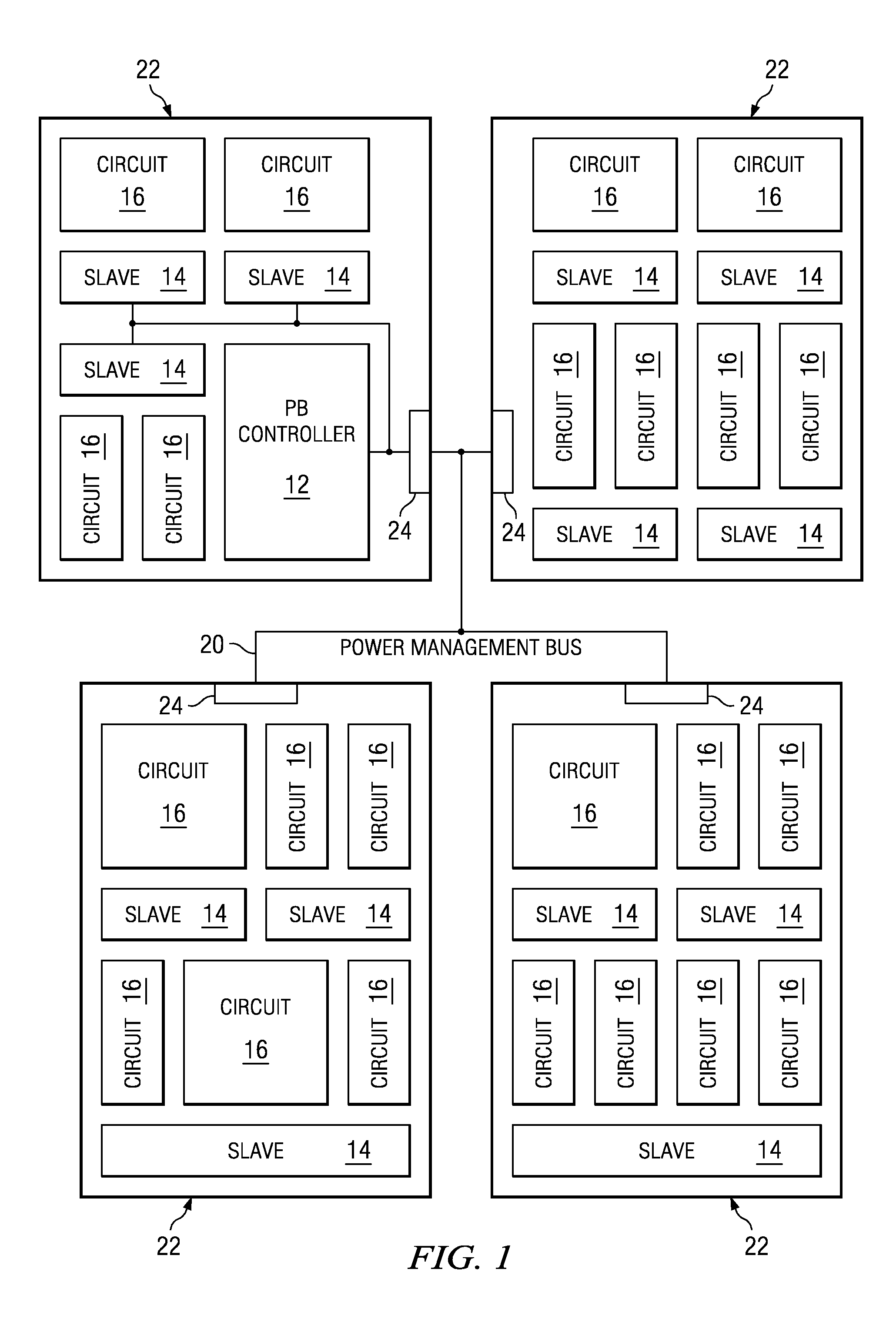
[0019]FIG. 1 illustrates a block diagram of an exemplary circuit using the power management system of the present invention. The present invention uses a single power management controller to drive multiple dislocated power resources. A power resource is an element of an integrated circuit, such as a regulator, a DCDC, a voltage reference, a current bias generator, a clock oscillator, or a reset generator. Each of the power resources can be optimized to provide power, clocks, or reset to a specific function.

[0020]In FIG. 1, a first integrated circuit (or “chip”) 10 contains a power bus controller 12 and one or more slave power management controllers 14. The slave power management controllers 14 are coupled to the power bus controller 12. Each slave power management controller controls the power for one or more circuits 16.

[0021]T...


PUM


Abstract

A power management bus for controlling power over multiple device subsystems includes a master power bus controller which transmits power management information to control one or more power resources through a transmit interface. The transmitted information is received at one or more receive interfaces. A broadcast message can be transmitted to control multiple power resources by subsystem, resource group and resource type. A single address message can be transmitted to control a single power resource. A power down can be initiated at any of the receive interfaces.

Description

CROSS-REFERENCE TO RELATED APPLICATIONS[0001]Not ApplicableSTATEMENT OF FEDERALLY SPONSORED RESEARCH OR DEVELOPMENT[0002]Not ApplicableBACKGROUND OF THE INVENTION[0003]1. Technical Field[0004]This invention relates in general to integrated circuits and, more particularly, to distributed power management of integrated circuits.[0005]2. Description of the Related Art[0006]Allocation of power in electronic circuitry is a primary concern in many areas, particularly in mobile circuitry, such as mobile telephones, PDAs (personal digital assistants), and other devices. As these devices become more complex and miniaturized, the need for effective power management increases, to both reduce power consumption (and, hence, optimize battery life) and to reduce heat generation.[0007]In the past, power resources have been clustered in a single power management chip which supplies power to multiple hardware resources (such as different processors, including digital signal processors or “DSPs”, copr...

Claims


Application Information

Patent Timeline
Patent Type & Authority Applications(United States)
IPC IPC(8): G06F1/26
CPCG06F1/3287Y02B60/1278G06F1/3203Y02B60/32Y02B60/1282Y02D10/00Y02D30/50
Inventor INDIANI, LORENZOJIGUET, JEAN-CHRISTOPHECARBOU, PIERREPERNEY, PHILIPPE
Owner COMPASS HORIZON FUNDING COMPANY
Why Eureka
Try Eureka