Scrubbing device and roll sponge assembly used therein

a technology of scrubbing device and roll sponge, which is applied in the direction of carpet cleaners, cleaning machines, cleaning equipment, etc., can solve the problems of high degree of smoothness, extremely difficult to maintain a high level of cleaning quality at all times, and reliably remove, so as to achieve high-efficiency scrubbing, without further complicated devices

Inactive Publication Date: 2008-11-13
FUJI ELECTRIC DEVICE TECH CO
View PDF3 Cites 9 Cited by
  • Summary
  • Abstract
  • Description
  • Claims
  • Application Information

AI Technical Summary

Benefits of technology

[0018]In the present invention, the pressing force of the roll sponge in the roll sponge assembly of the scrubbing device against a cleaning substrate can be varied continuously in accordance with the movement of the substrate by varying the outer diameter of the roll sponge. In other words, by moving the cleaning substrate in the lengthwise direction of the roll sponge as scrubbing process goes on, a pressing force corresponding to the cleaning stage can be provided between the roll sponge...

Problems solved by technology

However, when particles are adhered to the substrate, a high degree of smoothness cannot be obtained regardless of the precision with which the substrate is polished, and therefore the cleaning method employed after the precision polishing is extremely important.
Therefore, with respect to the required level of the cleanness and the size of the particles, it is extremely difficult to maintain a high level of cleaning quality at all the time.
As disclosed in Japanese Unexamined Patent Application Publication No. 2002-74653, with ultrasonic cleaning alone, comparatively large polishing agent residue can be removed, but it is still difficult to reliably remove minute residue such as those described above, and therefore a plurality of cleaning tanks is necessary, thereby increasing the cleaning time which adversely affects productivity.
(1) It is difficult to optimize the pressing force of the sponge against the substrate.
(2) When particles accumulate on the sponge, the substrate becomes recontaminated by the particles.
(3) A device for performing multi-stage scrubbing and overcoming problems...

Method used


Image

  • Scrubbing device and roll sponge assembly used therein
  • Scrubbing device and roll sponge assembly used therein
  • Scrubbing device and roll sponge assembly used therein

Examples


first embodiment

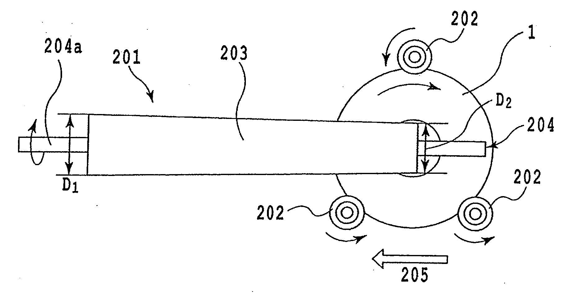
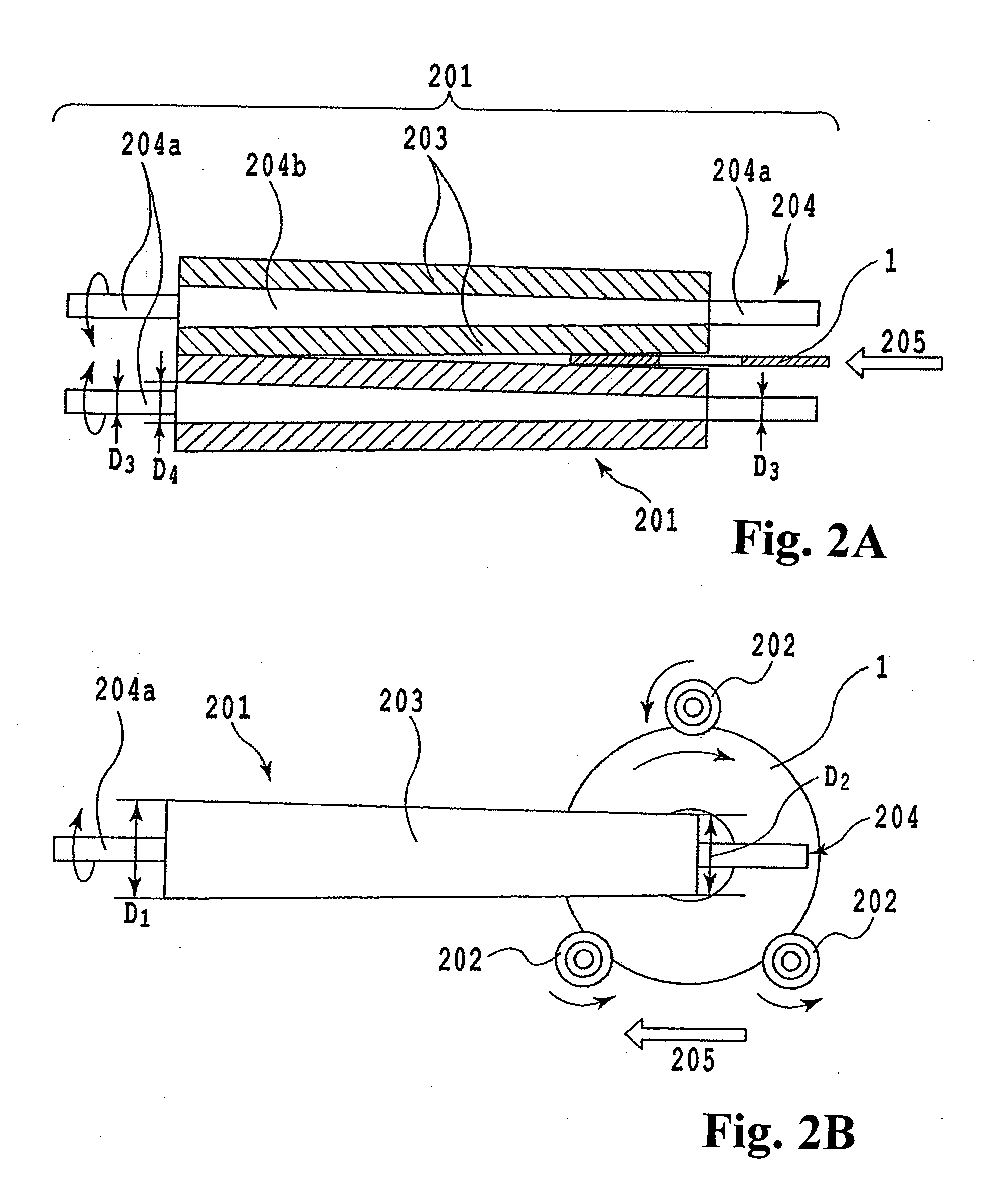
[0028]FIGS. 2A and 2B show schematic views of a scrubbing device according to a first embodiment of the present invention. FIGS. 3A to 3C show a substrate cleaning process performed by the scrubbing device. FIGS. 5A and 5B are views comparing the cleaning effects of the first embodiment and a conventional device. FIG. 6A is an exploded view of a roll sponge assembly used in the scrubbing device.

[0029]The scrubbing device of this embodiment basically comprises a plurality of rollers 202 for supporting and rotating a cleaning subject 1, and a pair of roll sponge assemblies 201 for cleaning the cleaning subject 1.

[0030]In the scrubbing device according to this embodiment, the cleaning subject 1 is an annular magnetic disk substrate. As is evident from FIG. 2B, the cleaning subject substrate 1 is supported vertically in a plurality of (three in this embodiment) support points around its peripheral edge by the plurality of (three in this embodiment) rollers 202. As shown in FIG. 2B, when...

second embodiment

[0045]FIG. 6B is an exploded view of a roll sponge assembly employed in a scrubbing device according to a second embodiment of the present invention.

[0046]This embodiment basically conforms to the first embodiment described above, but in consideration of the productivity of the expendable roll sponge 203, measures have been taken to adopt a conventional production method in which a constant-diameter roll sponge is simply cut for use. In other words, this embodiment differs from the first embodiment only in the structure of the roll sponge, and all other constitutions are completely identical to the first embodiment.

[0047]In this embodiment, as shown in FIG. 6B, a roll sponge assembly 401 includes a roll sponge 403 for cleaning a substrate and a support 404 for supporting the roll sponge 403.

[0048]The outer diameter of the outside contour of the roll sponge 403 according to this embodiment is constant in the lengthwise direction and equal to the minimum outer diameter D2 of the roll ...

third embodiment

[0054]FIG. 6C is an exploded view of a roll sponge assembly employed in a scrubbing device according to a third embodiment of the present invention.

[0055]This embodiment also conforms to the first embodiment described above, but improves the shape of the roll sponge and the support for fixing and supporting the roll sponge. Therefore, this embodiment differs from the first embodiment only in the structure of the roll sponge assembly, and is completely identical to the first embodiment in all other constitutions.

[0056]In this embodiment, as shown in FIG. 6C, a roll sponge assembly 501 includes a roll sponge 503 for cleaning a substrate and a support 504 for supporting the roll sponge 503.

[0057]Similarly to the roll sponge 203 of the first embodiment, the outside contour of the roll sponge 503 according to this embodiment has a conical trapezoid shape having an outer diameter that gradually increases from D2 to D1 in a right-left direction. A hollow hole 503c is formed in a central po...


PUM


Abstract

A roll sponge assembly for a scrubbing device includes a support having a support portion and a rotary shaft provided on two ends of the support portion, and a roll sponge having a hollow hole for holding the support by fitting the support portion of the support into the hollow hole. An outer diameter of the roll sponge assembly continuously or in stages increases in a lengthwise direction thereof.

Description

BACKGROUND OF THE INVENTION AND RELATED ART STATEMENT[0001]The present invention relates to a scrubbing device for cleaning a circular or a rectangular plate such as a magnetic disc substrate made of metal, glass or the like, a semiconductor wafer, and so on, and a roll sponge assembly used in the scrubbing device.[0002]In recent years, magnetic disk drives have become smaller in size and expanded their range of applications, while it has been always demanded to further increase a recording density of a magnetic disc installed in the drive. A magnetic disk is manufactured by forming thin films such as a magnetic layer on a substrate made of glass or a metal such as aluminum. With regard to this type of magnetic disk, major progress has been made, in response to the demands described above, for the development of a substrate capable of reducing the distance (magnetic spacing) between a magnetic head and the magnetic disk. As disclosed in Patent Document 1: Japanese Unexamined Patent ...

Claims


Application Information

Patent Timeline
IPC IPC(8): A46B15/00
CPCB08B1/04G11B5/8404H01L21/67046
Inventor SATO, NARUMI
Owner FUJI ELECTRIC DEVICE TECH CO
Why Eureka
Try Eureka