
Projectile and System for Providing Air-to-Surface Reconnaissance

a technology of air-to-surface reconnaissance and projectiles, applied in the direction of ammunition projectiles, weapons, aiming devices, etc., can solve the problems of inability to provide close-range reconnaissance to small combat units, inability to use satellite cameras, aircraft, drones, etc., and achieve the effect of improving position estimation

Inactive Publication Date: 2008-11-13
GEORGIA TECH RES CORP
View PDF3 Cites 25 Cited by
  • Summary
  • Abstract
  • Description
  • Claims
  • Application Information

AI Technical Summary

Benefits of technology

[0010]The descent of the reconnaissance equipment is slowed to permit a camera to take a number of photographs or other sensors collected data before reaching the surface of the earth. This descent can be regulated by a parachute, which is preferably vented to control the descent and prevent the spinning of the parachute and the reconnaissance equipment. The parachute and the reconnaissance equipment are housed in the separable section. A drogue, such as a simple aluminum plate, can be used to facilitate the parachute being deployed and filled with air. A camera can be set to commence taking pictures as soon as the separable unit is separated from the rest of the projectile or it can be delayed for a few seconds. The camera is preferably a CMOS on a chip. It can be either a still picture camera or a video. A wide angle lens is preferably provided. The image recorded by the digital camera is delivered via electronic data link to the ground as a digital stream which is processed by the receiver unit for display. Analog to digital conversion take place in the reconnaissance equipment. Once received, the scenes can then be transmitted in digital format to a receiver as normal jpeg images. A power source, such as a small battery, is provided to supply all the electrical power requirements for the reconnaissance equipment.
[0012]The reconnaissance equipment provided by this invention is capable of being placed in a regular mortar illumination round in which flare material is normally contained. This aerial reconnaissance projectile can be a conventional mortar round, artillery round, or rocket. A parachute or other means, such as braking fins on the reconnaissance equipment can be used to slow and control its descent over the surface to be viewed. The remote radio receiver is capable of receiving radio transmissions from the radio transmitter in the reconnaissance equipment. The radio receiver is usually located where, in the case of a mortar, it has a line of sight to the reconnaissance equipment during its descent. This radio receiver is connected to a viewing screen, such as in a personal computer. A specially adapted hand held viewing device that has a screen can be used. The trajectory model of the projectile can be stored in the personal computer or hand held video device so that the position of the view is displayed on the screen with appropriate scaling applied. An on-board inertia measuring unit (IMU) can be used to improve the position estimation in respect to the view displayed on the screen.

Problems solved by technology

However, the available technology does not have the practical capability of providing close range reconnaissance to small combat units, such as the squad.
If enemy positions on the other side of a hill or on the top of a building are undetected the chances of incurring casualties is significant.
Cameras on satellites, aircraft, and drones are usually either not capable or available to be utilized to meet the needs of an individual infantry squad or platoon, but are focused on a larger battlefield scene.

Method used


Image

  • Projectile and System for Providing Air-to-Surface Reconnaissance
  • Projectile and System for Providing Air-to-Surface Reconnaissance
  • Projectile and System for Providing Air-to-Surface Reconnaissance

Examples


Embodiment Construction

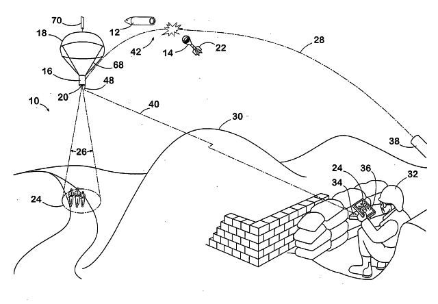
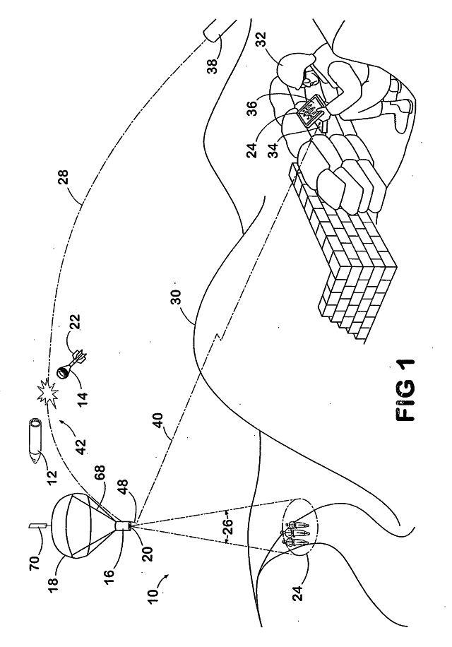
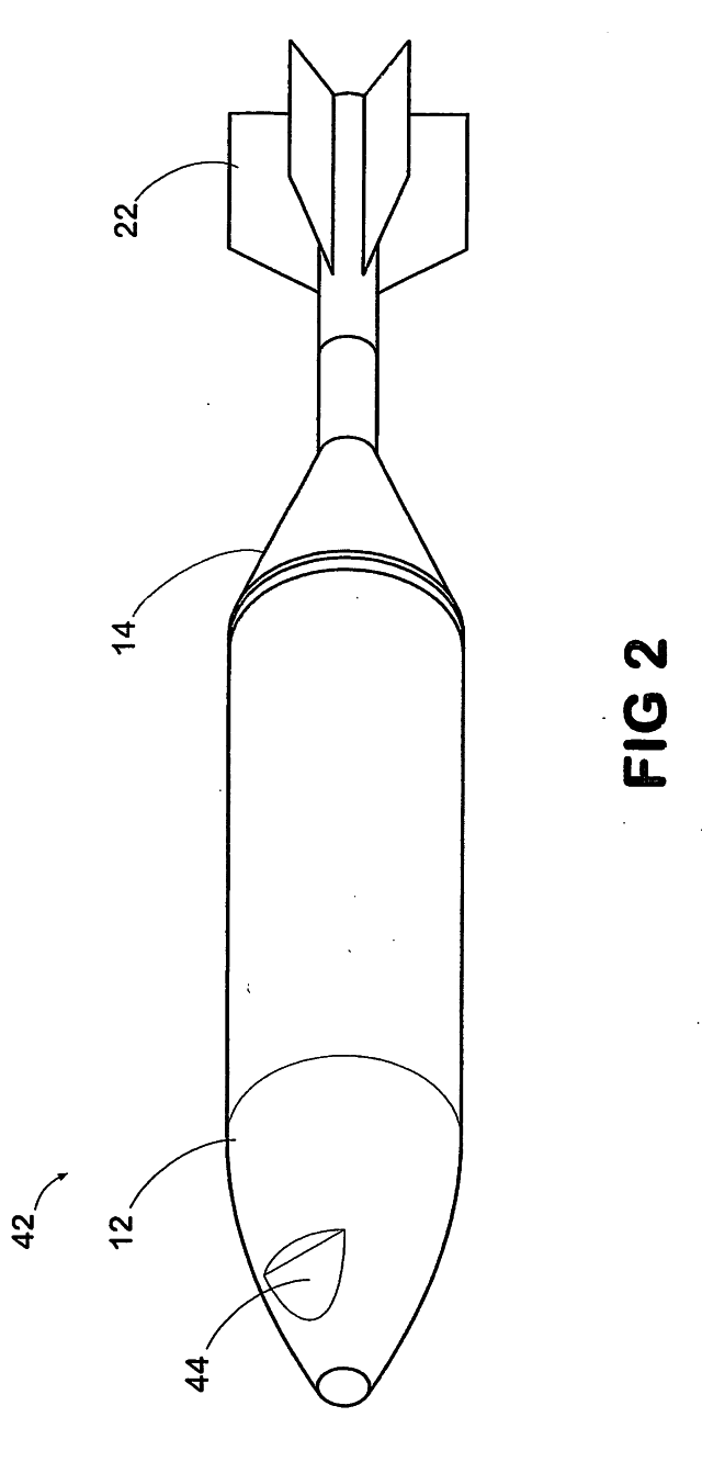
[0020]A perspective view of the method of this invention by which the reconnaissance equipment is used to view a scene that is obstructed from view is illustrated in FIG. 1. In this case the perspective view 10 is a view of a batttlefield scene. In this situation a mortar rotund has just been launched from the rocket tube 38 over the battlefield scene. The mortar round has been separated into a nose section 12 and a tail section 14 by a small explosion within the rocket round that cuts the pins (not shown) that hold the nose section 12 and the tail section 14 together. The reconnaissance section 16 has been pulled from the rocket round and is slowly descending over the scene to be viewed 24. This descent is slowed by a parachute 18. The reconnaissance section 16 has a camera 20 for viewing the battlefield scene 24 and transmitting the view by radio back to a radio receiver and computer 34 on the ground which is connected to a viewing screen 36 which can be viewed by the soldier 32. ...


PUM


Abstract

An aerial reconnaissance projectile, such as a mortar, is launched for viewing a battlefield scene. A reconnaissance section is released from the projectile and conveys back pictures of the battlefield scene taken by a camera and transmitted by radio to a ground position for viewing on a video screen. The reconnaissance section; may have an inertia measurement unit for determining its position over the battlefield scene. The projectile containing the reconnaissance equipment may be a convention mortar round or a rocket projectile. This aerial reconnaissance projectile is capable of carrying sensors for chemical, biological or nuclear activity on the surface area being traversed or intercepting radio signals from the ground and conveying this information by radio to a ground position with a radio receiver.

Description

CROSS-REFERENCE TO RELATED APPLICATION[0001]This application claims priority to copending U.S. provisional application entitled, “Exiting Projectile Alternative Payload For Air-To-Ground Reconnaissance,” having ser. no. 60 / 553,177, filed Mar. 15, 2004, which is entirely incorporated herein by reference.BACKGROUND OF THE INVENTION[0002]1. Field of the Invention[0003]A projectile for providing air to surface reconnaissance with a camera or other type of sensor that conveys the images or other data by a radio transmitter to a radio receiver that may be connected to a viewing screen at a remote location is provided.[0004]2. Prior Art[0005]Big strides have been made in the reconnaissance capability of the land battlefield in the last few decades with the advent of cameras carried on aircraft, drone vehicles and satellites. However, the available technology does not have the practical capability of providing close range reconnaissance to small combat units, such as the squad. A small infa...

Claims


Application Information

Patent Timeline
IPC IPC(8): F42B30/00
CPCF41G3/02F42B12/365
Inventor STANCIL, CHARLES M.
Owner GEORGIA TECH RES CORP
Learn More