Hot-Water Supply System Having Supplementary Heat Exchanger

Inactive Publication Date: 2008-11-13
KYUNGDONG NAVIEN
View PDF10 Cites 2 Cited by
  • Summary
  • Abstract
  • Description
  • Claims
  • Application Information

AI Technical Summary

Benefits of technology

[0013]The hot water supplying apparatus having an auxiliary heat exchanger according to the present invention, is provided with an auxiliary heat exchanger for raising the temperature of cold wa

Problems solved by technology

Such a temperature difference seriously occurs in winter when a temperature of water in heating pipes is very

Method used


Image

  • Hot-Water Supply System Having Supplementary Heat Exchanger
  • Hot-Water Supply System Having Supplementary Heat Exchanger
  • Hot-Water Supply System Having Supplementary Heat Exchanger

Examples


Example

[0017]Hereinafter, the structure and operation of a hot water supplying apparatus according to the present invention will be described in detail with reference to the accompanying drawings.

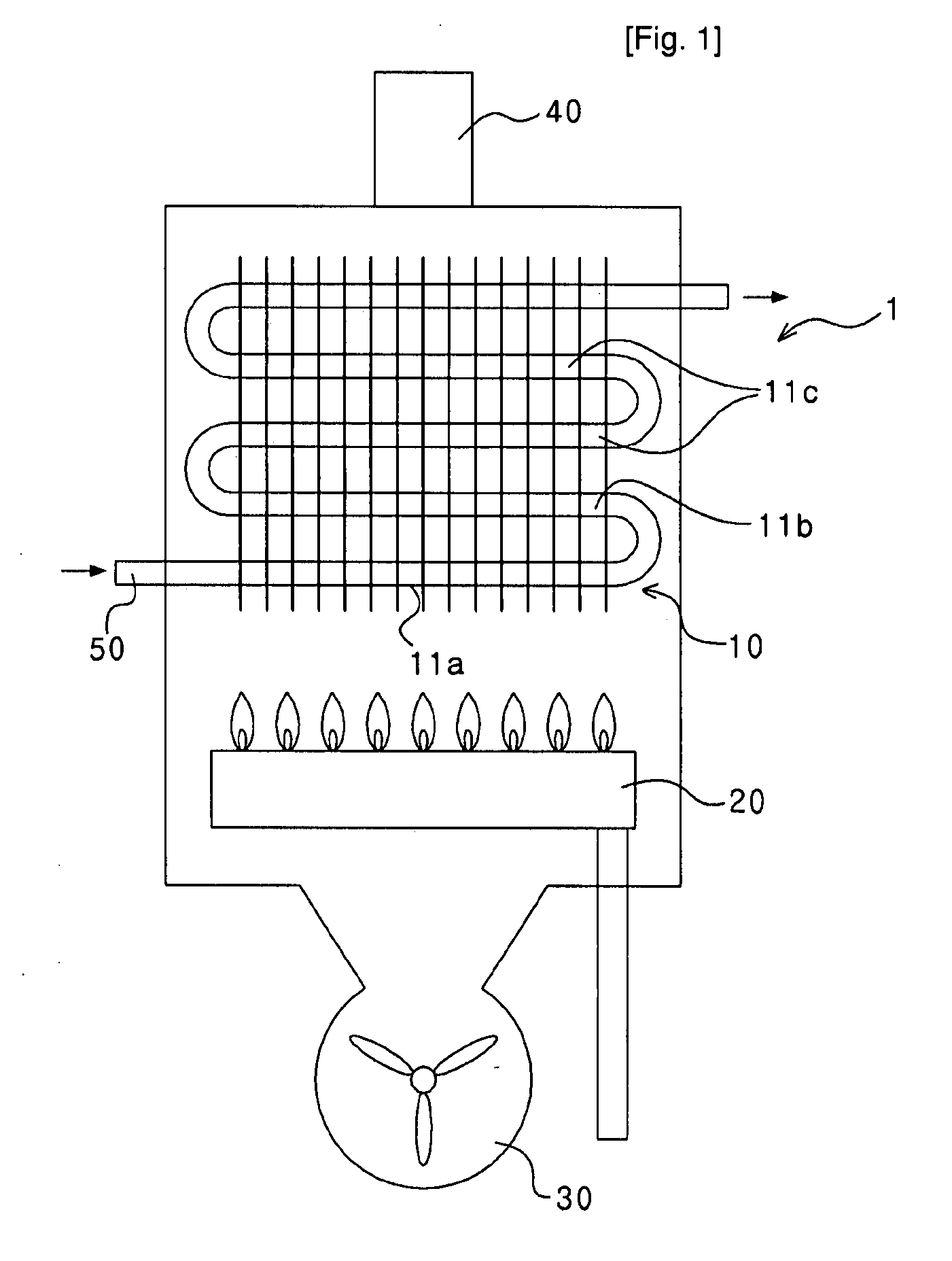
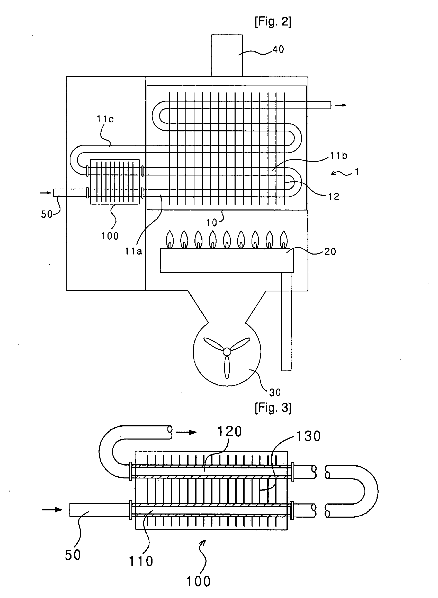
[0018]FIG. 2 is a schematic view showing a hot water supplying apparatus including an auxiliary heat exchanger according to an embodiment of the present invention.

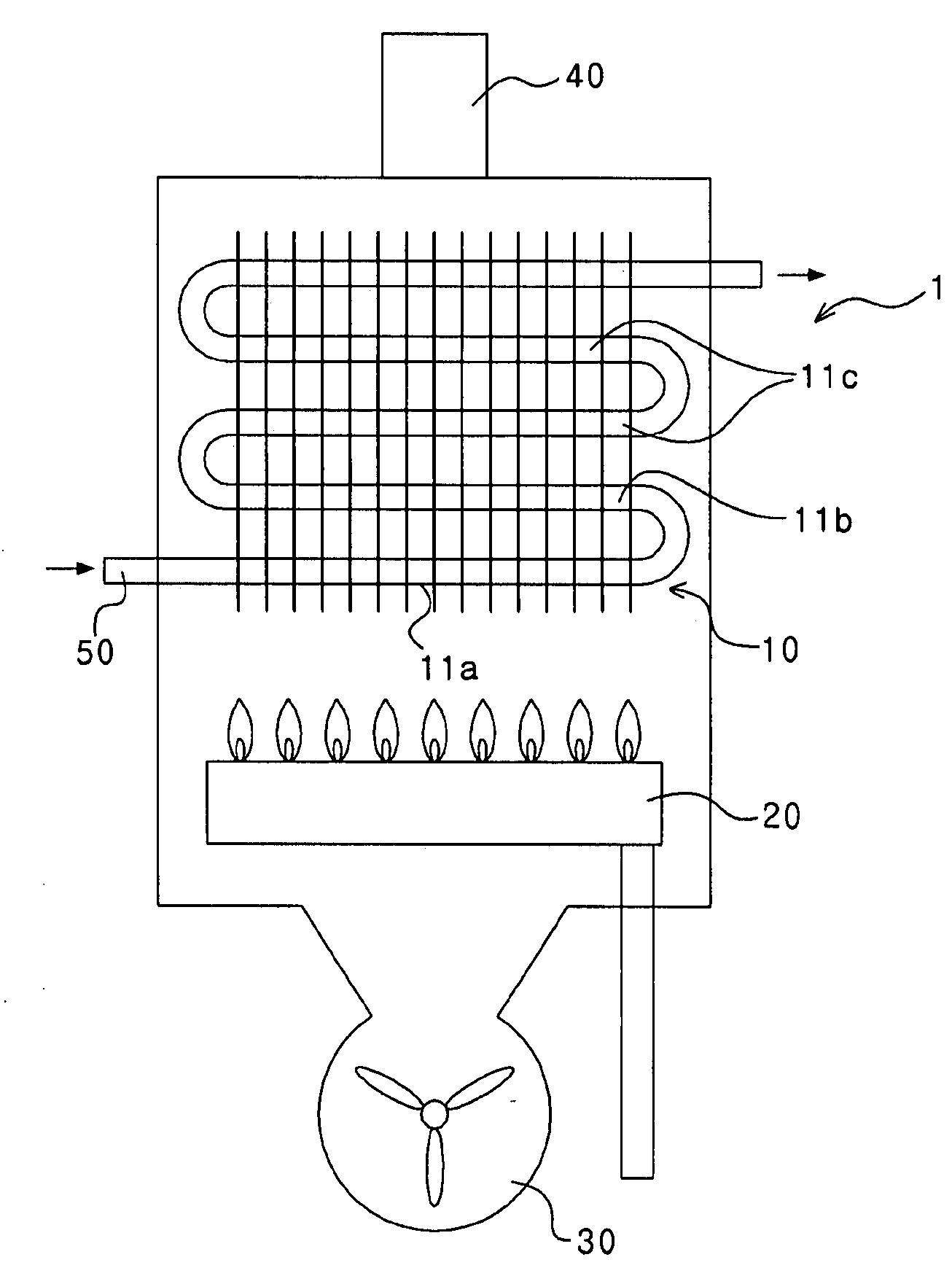
[0019]An inlet pipe 50 for a heat exchanger is installed at an inlet port of the heat exchanger 1 into which returned calefactory water, having finished a transfer of heat at a locations which require heating, is introduced.

[0020]A burner 20 is provided on the upper portion of a blower 30, on which a heat exchanging section 10 including a plurality of heat exchanging pipes connected to the inlet pipe 50 for the heat exchanger is arranged, so as to transfer heat energy from the burner 20 to calefactory water in the heat exchanging pipes.

[0021]The heat exchanging section 10 has a plurality of heat exchanging pipes including first, second, ...


PUM


Abstract

Disclosed is a hot water supplying apparatus having an auxiliary heat exchanger. The hot water supplying apparatus comprises: a heat exchanger including an inlet pipe for introducing heating water into the heat exchanger, and first, second, and third heat exchanging pipes connected to the inlet pipe and sequentially arranged; and an auxiliary heat exchanging device installed at an inlet port of the heat exchanger through which the heating water is introduced, the auxiliary heat exchanging device including a first auxiliary heat exchanging pipe connecting the inlet pipe to the first heat exchanging pipe, a second auxiliary heat exchanging pipe connecting the second heat exchanging pipe to the third heat exchanging pipe, and heat transfer fins for transferring heat energy from the second auxiliary heat exchanging pipe to the first auxiliary heat exchanging pipe.

Description

TECHNICAL FIELD[0001]The present invention relates to a hot water supplying apparatus having an auxiliary heat exchanger, and more particularly to a hot water supplying apparatus, which includes an auxiliary heat exchanger capable of preheating introduced calefactory water in order to prevent the creation of corrosion of pipe due to condensation at an inlet port of a heat exchanger through which the calefactory water is introduced.BACKGROUND ART[0002]In general, a heat exchanging apparatus provided to an apparatus for supplying hot water is to absorb combustion heat generated from a burner, and includes heat exchanging pipes through which water flows and heat transferring fins for absorbing the combustion heat, so as to heat water using the combustion heat in order to make hot water.[0003]FIG. 1 is a schematic view showing the structure of a conventional gas powered boiler.[0004]In a heat exchanging apparatus 1, heat energy generated by a burner 20 is transferred to a heat exchanger...

Claims


Application Information

Patent Timeline
IPC IPC(8): F24D19/00
CPCF24H1/145F24H9/0036F28D1/0417F28D1/0461F28D1/0477F28F1/32F24H1/41
Inventor MIN, TAE-SIK
Owner KYUNGDONG NAVIEN
Why Eureka
Try Eureka