Fire protection sprinkler system and related apparatus

a sprinkler system and sprinkler technology, applied in the field of sprinkler systems, can solve the problems of affecting the safety of the patient, the inability to install, and the detriment of the new construction advantage, so as to facilitate multiple connections, facilitate installation, and facilitate the effect of installation

Inactive Publication Date: 2008-11-13
THE WANDA GROUP
View PDF12 Cites 15 Cited by
  • Summary
  • Abstract
  • Description
  • Claims
  • Application Information

AI Technical Summary

Benefits of technology

The technical effect of this patented solution described in this patents relating to improving upon current methods used for installing temporary sprinkling systems has been improved safety measures during installation due to its ease-of-installability, ability to hide behind furniture when installed indoors, versatility across different types of pipe sizes, low cost per unit compared to traditional non-reusable options, and potential reduction in damages caused by fires. Additionally, there have also been improvements made over time through various means like adding ornamental elements around the tubes themselves.

Problems solved by technology

The technical problem addressed in this patent is the need for a concealable and cost-effective retrofit sprinkler system that can be easily installed in existing structures, particularly in cases where wall widths differ. Additionally, there is a need for attachment apparatus that can connect concealed sprinkler pipes to sprinkler heads at locations away from ceiling fans and lights.

Method used


Image

  • Fire protection sprinkler system and related apparatus
  • Fire protection sprinkler system and related apparatus
  • Fire protection sprinkler system and related apparatus

Examples


Embodiment Construction

[0031]It is to be noted that the appended drawing illustrates only typical embodiments of this invention and are therefore not to be considered limiting of its scope, for the invention may admit to other equally effective embodiments.

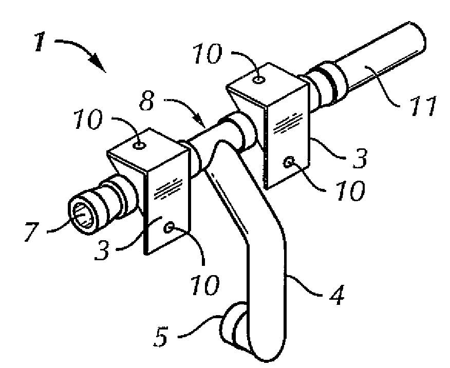
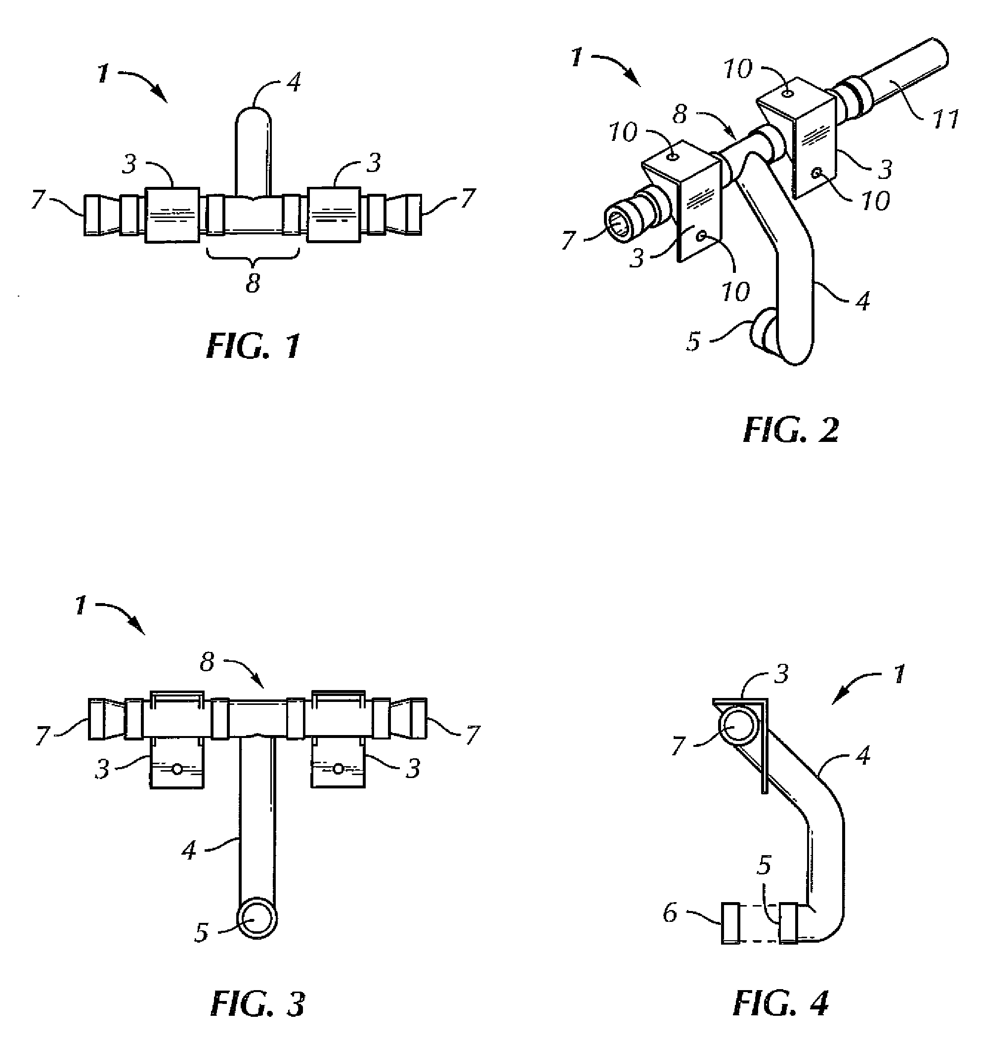
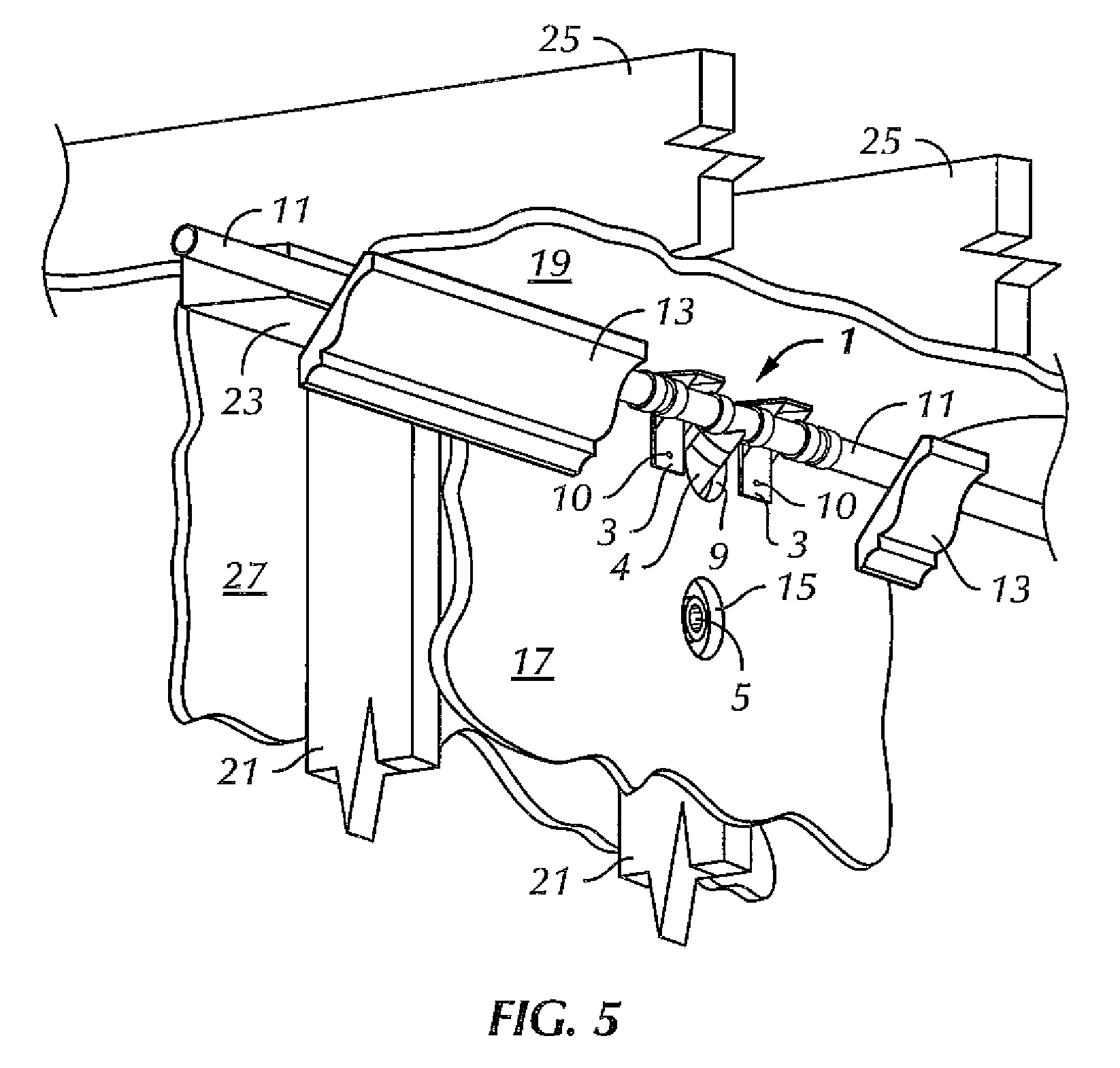
[0032]FIGS. 1-4 depict different views of a preferred sprinkler fitting 1 of the present invention. Sprinkler fitting 1 serves a primary function of securely connecting sprinkler head 6, represented schematically in FIG. 4, to sprinkler piping 11, thus placing the sprinkler head in fluid connection with a source of fire retardant fluid, which is typically water. A sprinkler head may be located on a wall surface, for instance, to avoid ornamental ceilings, fans, or impediments to ceiling placement. This is particularly the case in retrofitting jobs where sprinklers are being installed in pre-existing building structures, and where such structures have barriers such as wall top plates 23 (FIG. 6) that may obstruct access to the ceiling and placement of a ...


PUM


Abstract

A nondestructive retrofit fire sprinkler protection system including a sprinkler fitting with a unique shape that inserts behind a wall surface and that securely connects a sprinkler head emerging from a wall location to preferably concealed sprinkler piping located in a room at a point where the ceiling surface meets a wall surfaces. In addition, a room coupler fitting is adapted to be inserted between wall structures to connect sprinkler piping in adjacent rooms.

Description


Claims


Application Information

Patent Timeline
Owner THE WANDA GROUP
Why Eureka
Try Eureka