Capacitive type touch panel

a touch panel and capacitive technology, applied in the direction of instruments, capacitors with electrode area variation, pulse techniques, etc., can solve the problems of noise generation between, difficulty in identifying the location touched by the user,

Active Publication Date: 2008-11-13
TAZIK SOLUTIONS (SUZHOU) LTD
View PDF6 Cites 215 Cited by
  • Summary
  • Abstract
  • Description
  • Claims
  • Application Information

AI Technical Summary

Benefits of technology

[0007]The object of the present invention is to provide a capacitive type touch panel that can overcome the aforesaid drawback associated with the prior art.

Problems solved by technology

The gaps thus formed among the bonding wirings of the first and second wiring units 16, 17 are not fixed, which results in generation of noise between the first and second wiring units 16, 17, which, in turn, results in a difficulty in identifying the location touched by the user.

Method used


Image

  • Capacitive type touch panel
  • Capacitive type touch panel
  • Capacitive type touch panel

Examples


Embodiment Construction

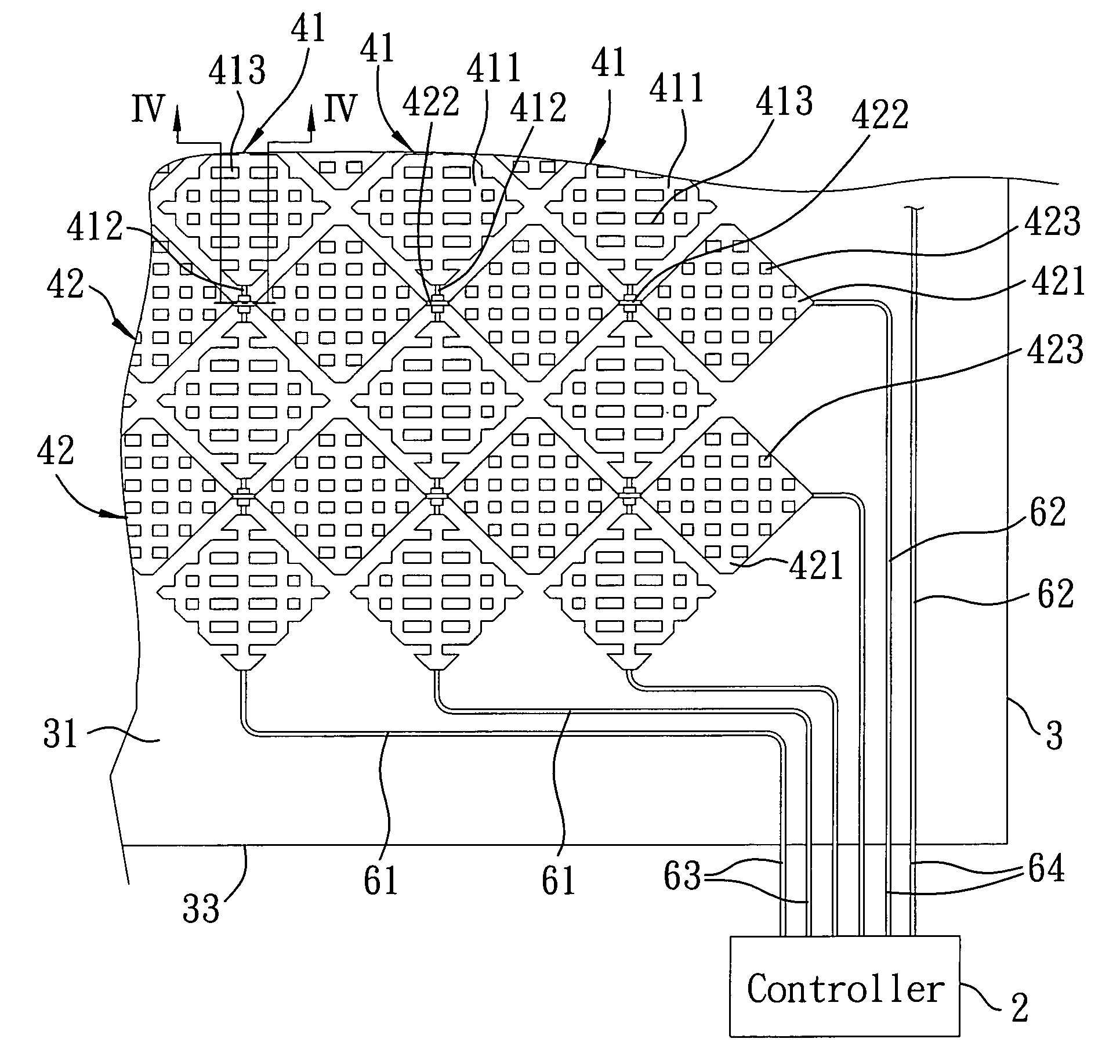
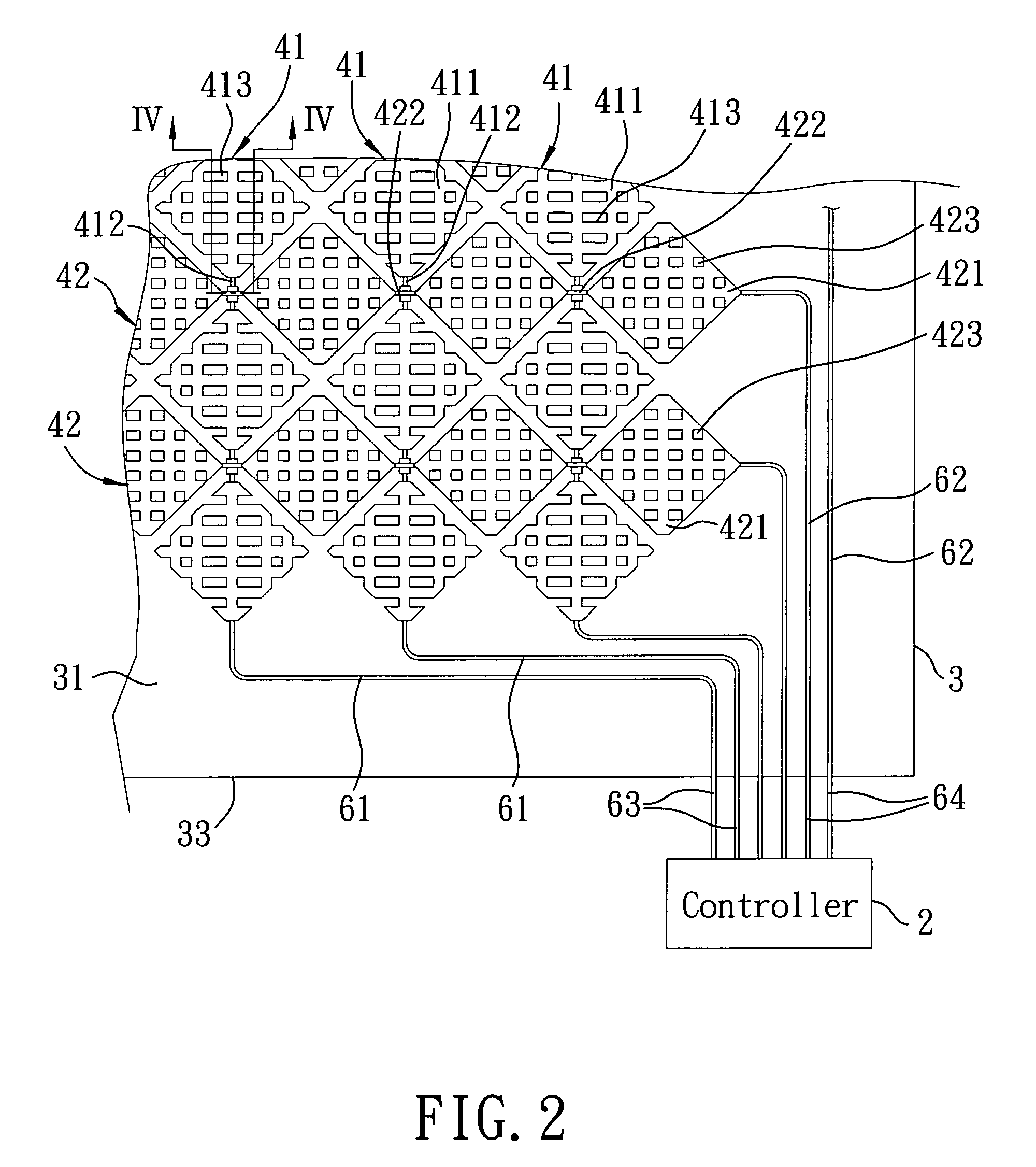
[0015]FIGS. 2 to 5 illustrate the preferred embodiment of a capacitive type touch panel according to this invention. The capacitive type touch panel includes: a transparent substrate 3 having opposite top and bottom surfaces 31, 32; an array of first conductors 41 formed on the top surface 31 of the transparent substrate 3; an array of second conductors 42 formed on the top surface 31 of the transparent substrate 3 and disposed alternately with the first conductors 41; a plurality of spaced apart conductive first bridging lines 412, each of which interconnects two adjacent ones of the first conductors 41; a plurality of spaced apart conductive second bridging lines 422, each of which interconnects two adjacent ones of the second conductors 42 and each of which intersects insulatively a respective one of the first bridging lines 412; and a plurality of spaced apart insulators 5, each of which is disposed at an intersection of a respective one of the first bridging lines 412 and a res...


PUM


Abstract

A capacitive type touch panel includes: a transparent substrate; an array of first conductors formed on a surface of the transparent substrate; an array of second conductors formed on the surface of the transparent substrate; a plurality of conductive first bridging lines, each of which interconnects two adjacent ones of the first conductors; a plurality of conductive second bridging lines, each of which interconnects two adjacent ones of the second conductors and each of which intersects insulatively a respective one of the first bridging lines; and a plurality of spaced apart insulators, each of which is disposed at an intersection of a respective one of the first bridging lines and a respective one of the second bridging lines to separate the respective first and second bridging lines.

Description

CROSS-REFERENCE TO RELATED APPLICATION[0001]This application claims priority of Taiwanese Application No. 096116883, filed on May 11, 2007.BACKGROUND OF THE INVENTION[0002]1. Field of the Invention[0003]This invention relates to a capacitive type touch panel, more particularly to a capacitive type touch panel including arrays of first and second electrodes formed on the same surface of a transparent substrate and disposed alternately with each other.[0004]2. Description of the Related Art[0005]FIG. 1 illustrates a conventional capacitive type touch panel that includes a transparent substrate 11, a first electrode unit 12 formed on a top surface of the transparent substrate 11, a second electrode unit 13 formed on a bottom surface of the transparent substrate 11, a conductive first connecting line unit 14 connected to the first electrode unit 12, a conductive second connecting line unit 15 connected to the second electrode unit 13, and conductive first and second wiring units 16, 17 ...

Claims


Application Information

Patent Timeline
Patent Type & Authority Applications(United States)
IPC IPC(8): H03K17/96
CPCG06F3/044G06F2203/04111H03K17/9622H03K2017/9602G06F3/0446
Inventor CHANG, YU-HUEI
Owner TAZIK SOLUTIONS (SUZHOU) LTD
Why Eureka
Try Eureka