
Remote Display and Control for Test and Measurement Apparatus

a technology of remote display and control, applied in the direction of digital variable/waveform display, cathode-ray oscilloscope, instruments, etc., can solve the problems of affecting the user experience, the test and measurement device cannot be positioned too far from the device under test, and the instrument requires a large footprin

Inactive Publication Date: 2008-11-13
LECROY
View PDF20 Cites 24 Cited by
  • Summary
  • Abstract
  • Description
  • Claims
  • Application Information

AI Technical Summary

Benefits of technology

[0011]Therefore, in accordance with the invention, a test and measurement apparatus is provide

Problems solved by technology

The debugging of electronic hardware requires a complex arrangement of test probes, cables and equipment connecting the device under test to the measurement equipment.
These measurement instruments require a good deal of bench space for their footprint, and are constantly in competition with the object under test for scarce bench space.
Unfortunately, the test and measurement device cannot be positioned too far from the device under test, because the user must frequently interact with the control knobs and buttons in order to adjust the most frequently used settings of the test and measurement apparatus.
The affection of end-users for physical knobs and buttons poses an additional dilemma for users that wish to control their instrument from a lengthy remote distance.
However the generic local computing device lacks the standard “short-cut” physical knobs and buttons that the user has become accustomed to using to control the instrument, thus decreasing the user's efficiency in using the device.

Method used


Image

  • Remote Display and Control for Test and Measurement Apparatus
  • Remote Display and Control for Test and Measurement Apparatus
  • Remote Display and Control for Test and Measurement Apparatus

Examples


Embodiment Construction

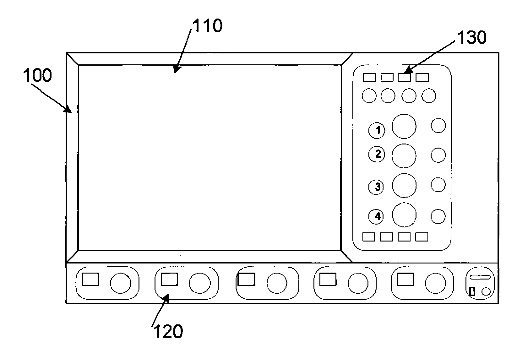
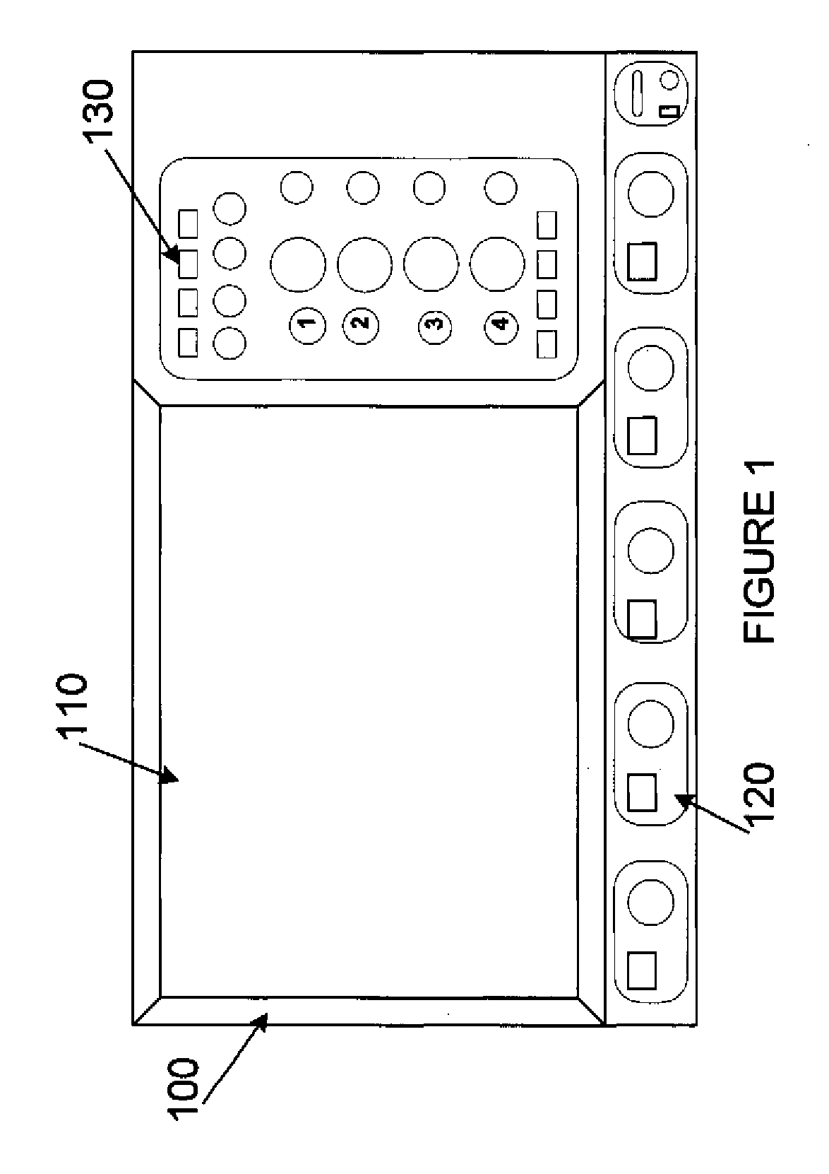
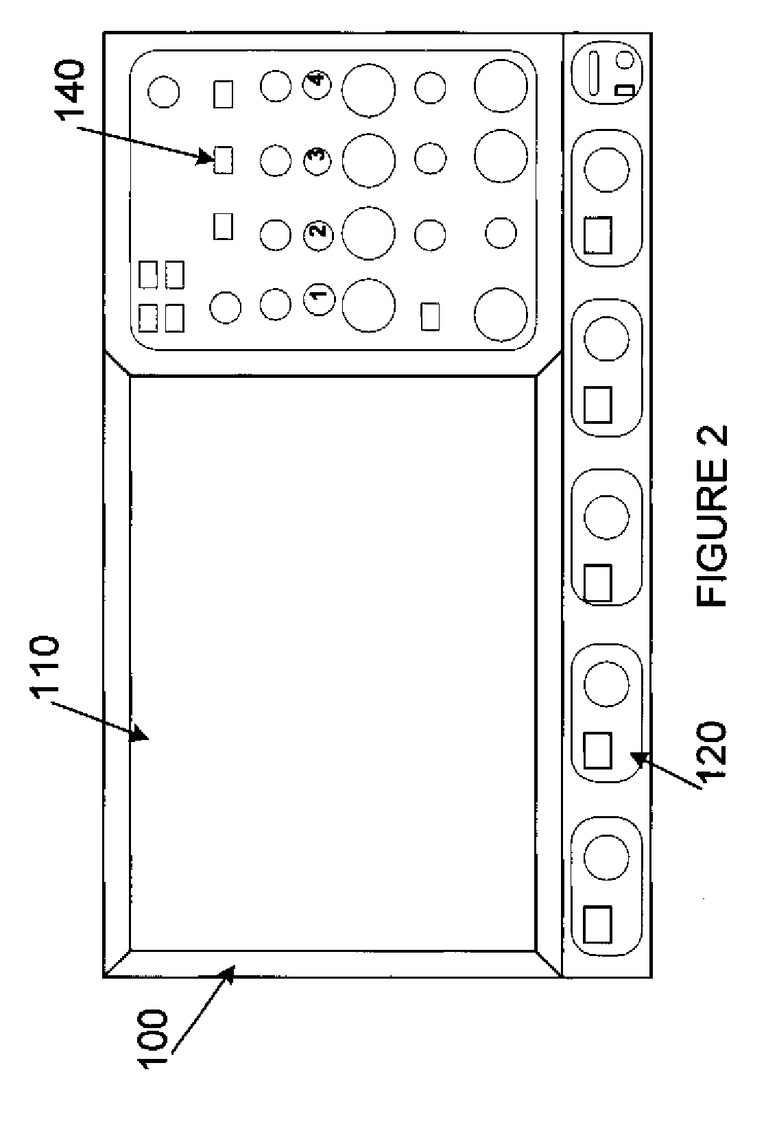
[0022]Referring first to FIG. 1, an oscilloscope 100 is shown. While the invention is described making reference to an oscilloscope, it should be understood that the invention is intended to apply to any type of test and measurement equipment, and to any apparatus including a display and an accompanying control panel. Oscilloscope 100 is preferably provided with a display 110, input / output ports 120 and a control panel 130. Control panel 130 includes knobs, indicators, buttons and the like as is well known in the industry. In FIG. 1, control panel 130 is depicted in a traditional location, thus providing a conventional oscilloscope layout. However, as will be discussed below, control panel 130 is in fact a removable control panel constructed in accordance with the invention, located in a conventional position.

[0023]In addition to the layout described, the control panel may be provided with a pointing device such as a track ball, joystick or other pointing mechanism. In such a manner...


PUM


Abstract

A remote display for a test and measurement apparatus is provided including a control panel. The control panel is removable and user-replaceable with an alternate control panel. The control panel can be connected to the remote display device to control and interact with the test and measurement apparatus, and to control the display of information on the remote display device.

Description

CROSS REFERENCE TO RELATED APPLICATIONS[0001]This application is a continuation in part application of U.S. patent application Ser. No. 12 / 132,660 filed Jun. 4, 2008, titled “Removable Front Panel Control for Oscilloscope”, currently pending, the contents thereof being incorporated herein by reference, which application in turn claims the benefit under 35 USC 119 of U.S. Provisional Patent Application Ser. No. 61 / 025,937 filed Feb. 4, 2008, titled “Removable Front Panel Control for Oscilloscope”, currently pending, the contents thereof being incorporated herein by reference. The Ser. No. 12 / 132,660 application is also a continuation in part application of U.S. patent application Ser. No. 11 / 641,154 filed Dec. 19, 2006, titled “Resizable Display”, currently pending, the contents thereof being incorporated herein by reference.FIELD OF THE INVENTION[0002]This invention is related generally to the collection of control buttons and knobs (configured to be manipulated as a cohesive contro...

Claims


Application Information

Patent Timeline
IPC IPC(8): G01R13/20
CPCG01R1/025G01R13/02H05K5/0017H05K5/0018
Inventor COX, TYLERCAKE, ANTHONYKIM, SUN Y.PASICHNYK, JOHNDAVE, VRAJESH
Owner LECROY
Learn More