
Adjustable fast set antenna frame

Inactive Publication Date: 2008-11-13
STEELHEAD METAL & FAB
View PDF7 Cites 8 Cited by
  • Summary
  • Abstract
  • Description
  • Claims
  • Application Information

AI Technical Summary

Benefits of technology

[0010]This embodiment bypasses the need to lift a completely assembled antenna frame that can be upwards of twelve feet wide and eight hundred pound up an elevated tower by dividing the antenna frame into three easy to manage components. This embodiment allows flexibility of the position of the antenna in accordance to the vertical tower and horizontal support frame and can be assembled in less time and in safer manner than the prior art.

Problems solved by technology

Therefore, the sector frames themselves are often extremely heavy and bulky.
The obvious disadvantage to assembling the sector frame away from the tower is that it will require a great deal of effort to lift the finished produce up the tower.
Furthermore, lifting and attaching a sector frame that can exceed twelve feet in width to an elevated structure can be overly challenging, especially if the tower is also surround by preexisting power or telephone cables.
However, this still required the installer to pull and install the entire antenna frame at once to the top of a tower.
The problem regarding weight and maneuverability remains unsolved.

Method used


Image

  • Adjustable fast set antenna frame
  • Adjustable fast set antenna frame
  • Adjustable fast set antenna frame

Examples


Embodiment Construction

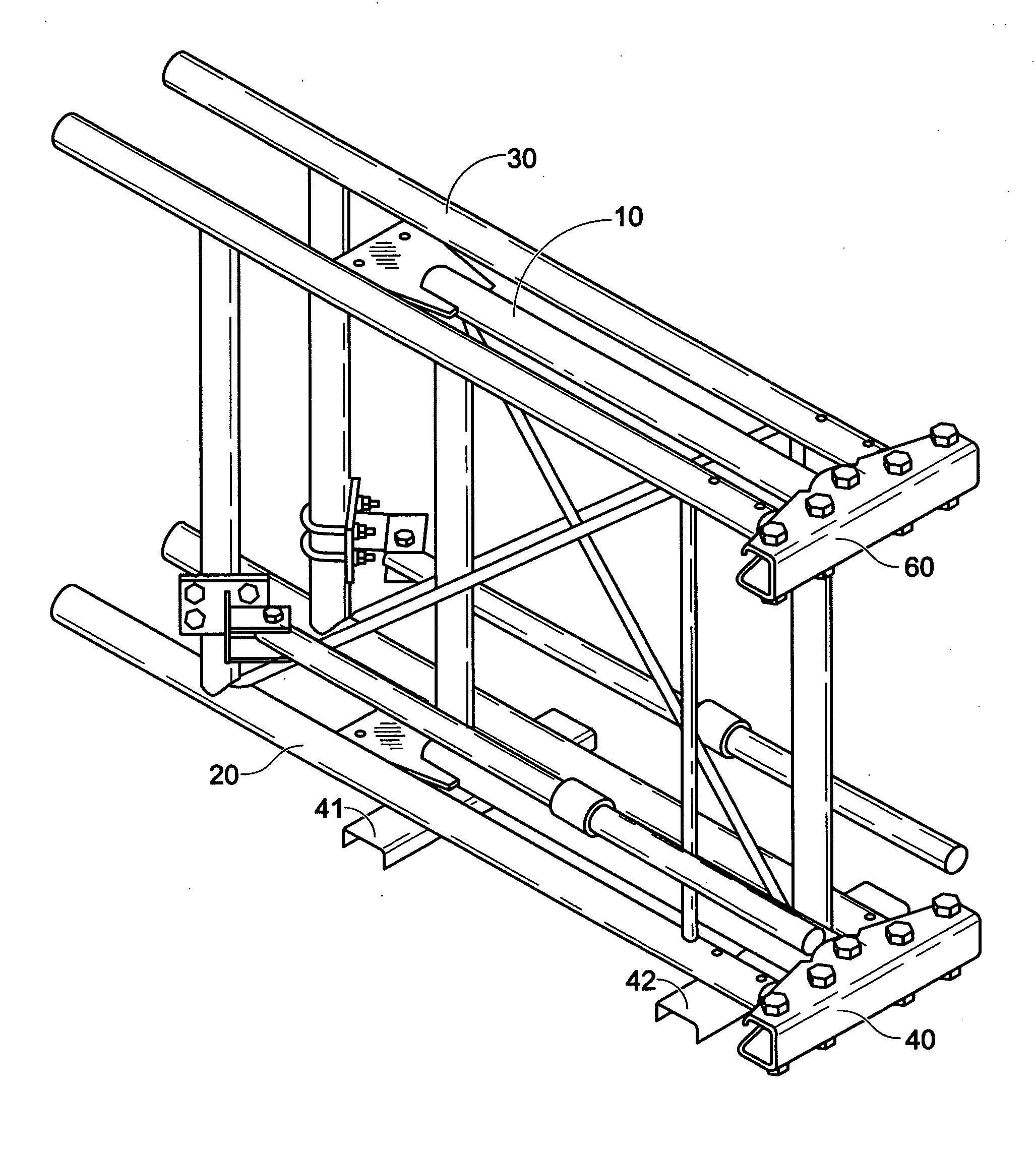
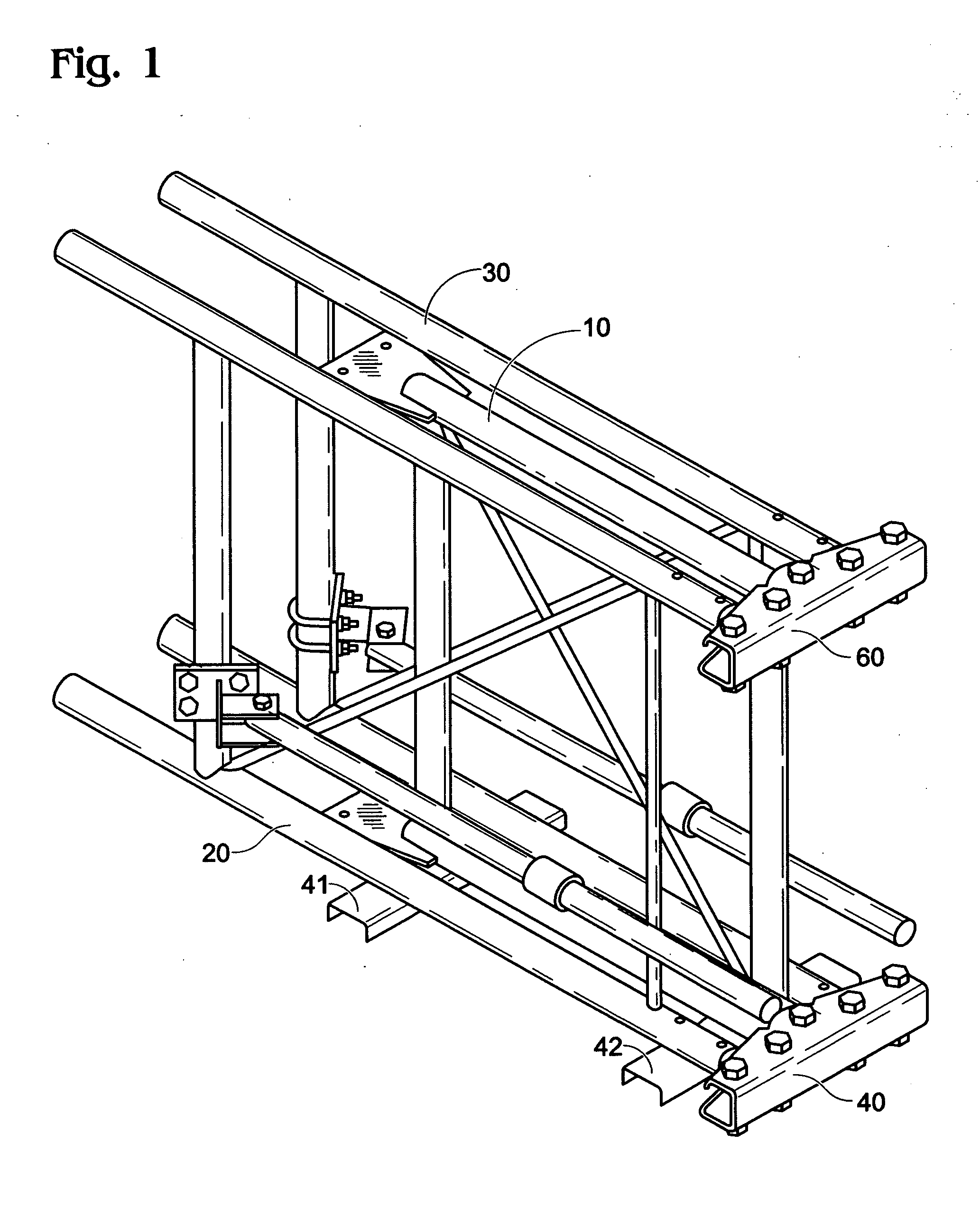
[0023]FIG. 1 depicts an isometric view of the shipping and storage state of the Fast Set Antenna Frame, according to an embodiment.

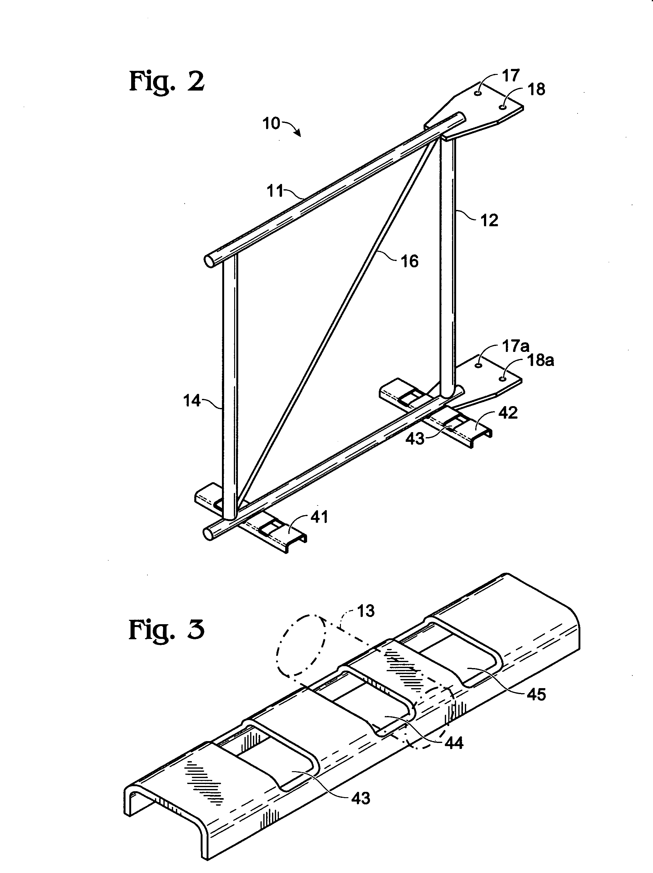
[0024]During the storage and shipping stage of the Fast Set Antenna Frame, the three preassembled frames, including the support frame 10, face frame 20, and face frame 30, rest in the groves of the storage base 41 and 42. This storage system improves on the prior art by allowing the Fast Set Antenna Frame to be stored and shipped in more of a compact form, thus reducing the storage space needed and the resource required to move the embodiment.

[0025]Furthermore, as seen in this view, the two face frames are not attached to the support frame during storage. Unlike the prior arts which have the face frames pre-attached and folded, the Fast Set Antenna Frame comes in three unattached frames so that during the installation phase, the installers can install one frame at a time. This allows the installer to better manage the weight and size of the antenna frame...


PUM


Abstract

This invention pertains to antenna sector frame that can be more easily installed. The frame is comprised of a support frame having a first vertical end, a second vertical end, an upper horizontal end, and a lower horizontal end. The first vertical end of the support frame may be connected to at least one mounting bracket and the second vertical end of said support frame may be connected to at least one curved T-housing, wherein the lower horizontal end of the support frame is connected to at least one storage base. The face frames comprises of a first vertical end and a second vertical end, wherein the first vertical end may be attached to the curved T-housing.

Description

CROSS-REFERENCE TO RELATED APPLICATIONS[0001]This application contains disclosure from and claims the benefit under Title 35, United States Code, §119(e) of the following U.S. Provisional Application: U.S. Provisional Application Ser. No. 60 / 917,661 Filed May 13, 2007 entitled ADJUSTABLE FAST SET ANTENNA FRAME.BACKGROUND OF THE INVENTION[0002]1. Field of Invention[0003]The present invention relates to sector frames for attaching of antennas onto utility power transmission structures or other vertical or of like kind structures.[0004]2. Background of the Invention[0005]It has been common practice in the telecommunication industry to bypass the cost and difficulties of constructing antenna towers by attaching antennas to preexisting power towers or structures of similar utility. This embodiment pertains to the mounting frame used to attach such antennas to tower structure in a safe, efficient and secure way.[0006]The process of adding antennas to a tower structure requires a stable se...

Claims


Application Information

Patent Timeline
IPC IPC(8): H01Q1/12
CPCH01Q1/1235
Inventor KREITZBERG, MICHAELVAUGHN, DAVID B.RADDATZ, KEVIN A.
Owner STEELHEAD METAL & FAB
Learn More