
Honeycomb structure, honeycomb structure type catalyst and production methods therefor

Active Publication Date: 2019-06-27
N E CHEMCAT
View PDF0 Cites 3 Cited by
  • Summary
  • Abstract
  • Description
  • Claims
  • Application Information

AI Technical Summary

Benefits of technology

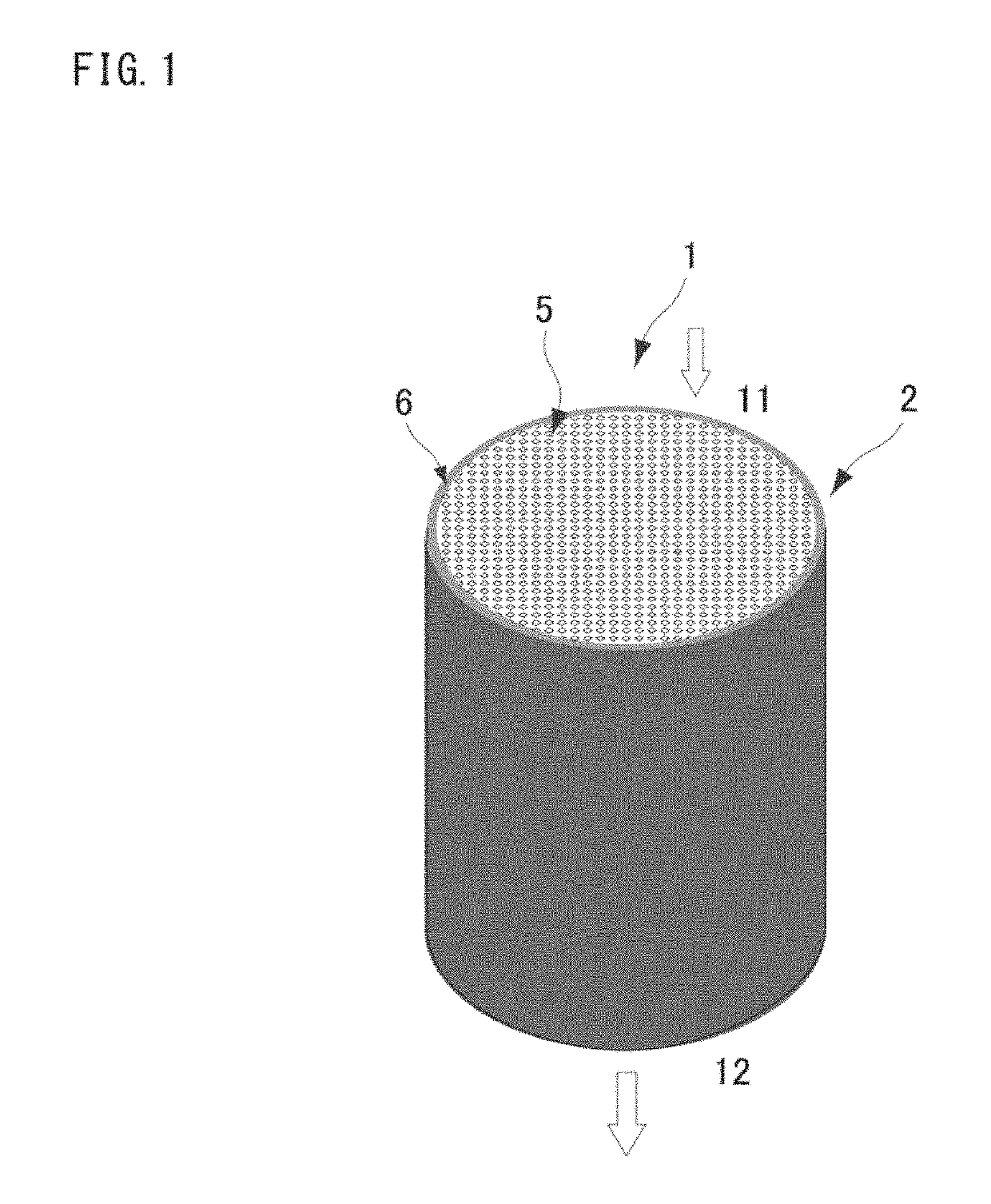
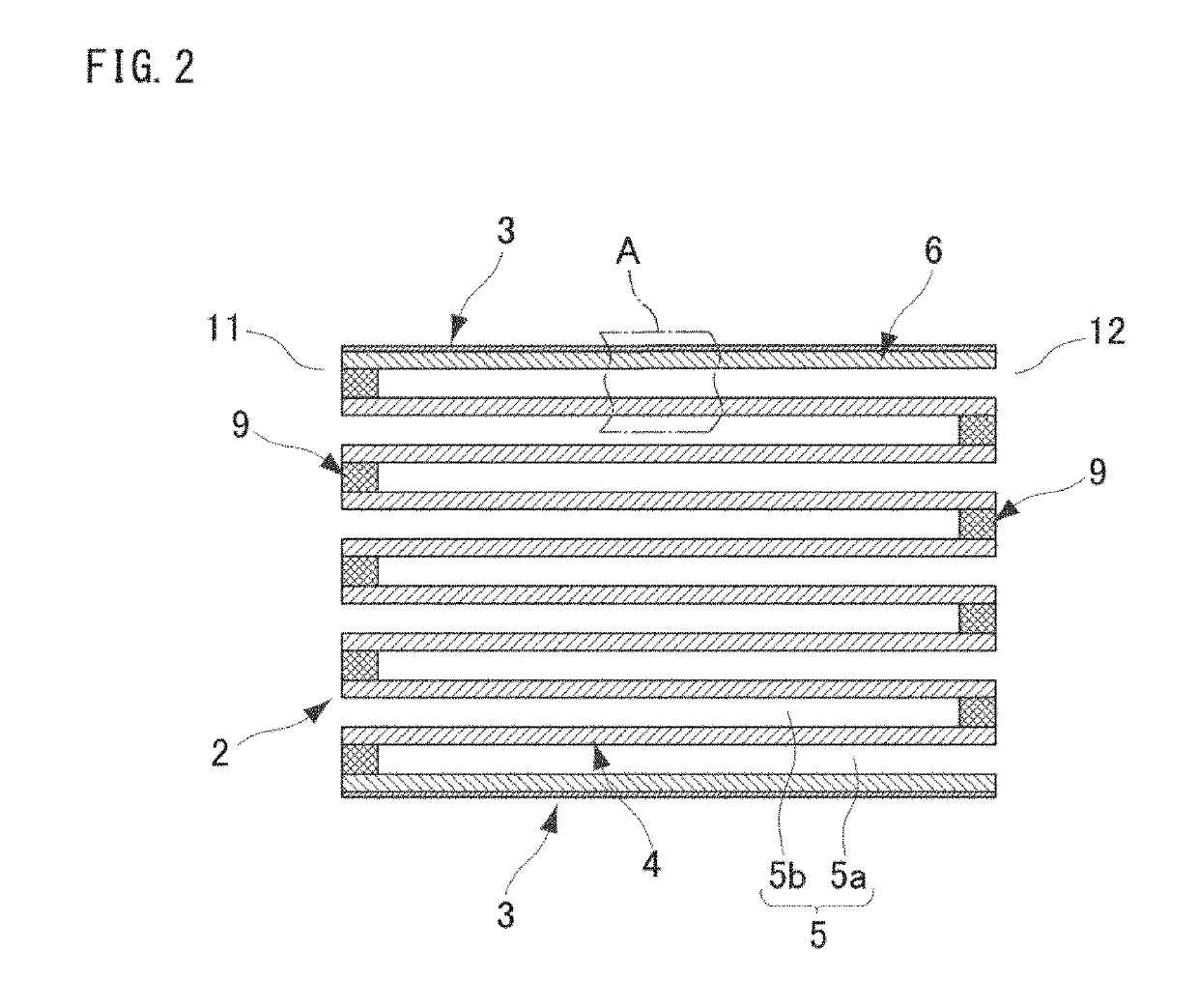
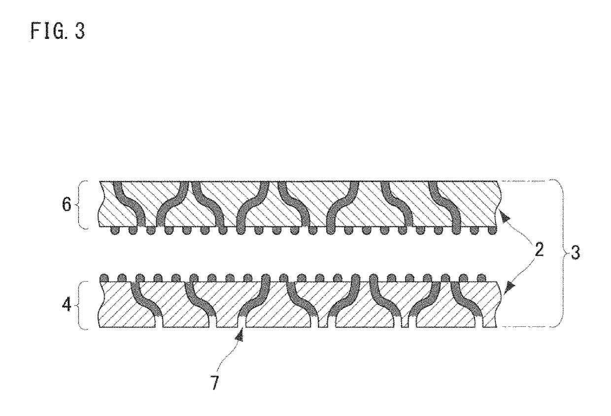
The present invention relates to a honeycomb structure with a resin composition completely impregnated into the pores of the outer portion. The depth of impregnation is the thickness of the outer portion. This results in complete blocking of all pores in the outer portion and prevents catalyst slurry from entering the outer portions during the production process, which is beneficial for the wash coating apparatus and reduces the loss of valuable metals. Additionally, the honeycomb structure type catalyst does not cause an increase in pressure loss or cracking due to heat history while traveling or during the catalyst production process. This results in stable exhaust gas purification performance as a GPF.

Problems solved by technology

PM filtered out from exhaust gas through the DPF is continuously deposited on the DPF, whereby clogging occurs.
However, gasoline-powered cars that use fuel with less PM generated have not been particularly focused as an environmental problem up until now.
With growing concerns over the environmental issues these days, however, restriction on harmful substances in exhaust gas has become stricter, and the amount of PM exhausted from gasoline-powered cars has also come to be restricted.
However, in these gasoline direct injection (GDI) type engines, the interior of the combustion chamber is in a combustion state while part of the atomized gasoline injected into the combustion chamber is maintained in a form of particles, so that incomplete combustion attributed to particle-like fuel occurs, and in some cases, a larger amount of PM is generated than from conventional gasoline-powered cars using an intake manifold from which a mixed gas including fuel and the air is supplied.
However, for the reasons as follows, due to characteristics of gasoline-powered cars, it is not easy for gasoline-powered cars to use the same DPF as that for diesel-powered cars.
Using the conventional DPF for such exhaust gas with high velocity would increase the back pressure of the engine, which obstructs improvement of engine output power.
Furthermore, if the outer portion of the honeycomb structure (hereinafter, it may be referred to as outer peripheral wall) has a wall made of another material, there may be a concern over cracking due to difference in the thermal expansion coefficient in a catalyst for gasoline engines, the temperature of which during traveling is higher than that of diesel engines.
Using the GPF enables removal of PM from exhaust gas without causing the back pressure to easily increase, but at the same time, a new problem has emerged in producing it as a catalyst.
However, the GPF has a problem in suppressing back pressure increase, and thus the outer peripheral wall of the GPF needs to be formed of a porous material having air permeability as in the case with the partition walls of the cells to enable exhaustion also from the outer portion, using a honeycomb structure having a porosity of 50% or higher, or more specifically 60% or higher.
In addition, since such a small honeycomb is used, the geometric area thereof as a filter is also small, and there is a great concern over output reduction associated with pressure loss.
However, the ends of the honeycomb cells are plugged, and the plugged portions are obstructive in “step of discharging the supplied slurry in the cell with air pressure” during wash coating, and thus the slurry discharged with air pressure leaches out from the outer portion.
Slurry thus leaching out from the outer portion not only contaminates a wash coating apparatus but also wastes the valuable noble metals.
Moreover, if the valuable noble metal components for an automotive catalyst, which are strictly managed in ingredient amount for cost savings, leach out from the outer portion, it makes it difficult to manage the ingredient amount to cause unevenness of the ingredient amount.
This unevenness in the ingredient amount is regarded as a defect in production.
Furthermore, the automotive catalyst achieves industrially implementable performance only when the ingredient amount is properly managed.
Slurry leaching out to the outer portion makes it difficult to manage the amount of catalyst supported on each honeycomb structure during mass production, and thus makes it extremely difficult to provide stable purification performance.
When the catalyst slurry penetrates to the outer portion of a porous honeycomb such as the GPF, a difference in the thermal expansion coefficient occurs between the components in the slurry and the material of the honeycomb, so that, in some cases, cracking occurs during the firing in the catalyst production process or during the cooling processing after this firing, or due to the heat history when the car is traveling.
As described above, in the wall-flow honeycomb for the GPF, the porosity is high in order to reduce the pressure loss, and since the outer peripheral wall is also of a porous material having air permeability as with the cell partition walls, occurrence of cracking due to penetration of the catalyst slurry is serious.
Furthermore, since the catalyst slurry contains a large amount of fine particles of inorganic oxides such as alumina along with active noble metals, cracking is further promoted by the influence of the inorganic oxide particles impregnated into the outer peripheral wall.
Moreover, the catalyst component filling up micro cracks existing in the honeycomb outer portion with a catalyst component impairs the ability to handle the stress caused by the difference in the thermal expansion coefficient, and cracking occurs as a result (for example, refer to Patent Document 8).
If a catalyst component exists on the outer peripheral wall of the honeycomb, cracking may occur due to the reason such as uneven temperature distribution when a temperature difference occurs between the outer circumferential part and the inner part due to the difference in thermal conductivity.
However, preventing catalyst slurry from leaching out when a porous honeycomb structure having excellent air permeability even on the outer peripheral wall as with the honeycomb for the GPF, and improving isostatic strength are not considered, or cracking due to heat history at the time of producing the catalyst or at the time of using the GPF is not taken in to consideration.

Method used


Image

  • Honeycomb structure, honeycomb structure type catalyst and production methods therefor
  • Honeycomb structure, honeycomb structure type catalyst and production methods therefor
  • Honeycomb structure, honeycomb structure type catalyst and production methods therefor

Examples


working examples

[0179]Hereinafter, the present invention will be described in more detail on the basis of working examples, but the invention is not limited to these examples.

(Honeycomb Substrate)

[0180]As a base material of the honeycomb structure, a cordierite made wall-flow honeycomb manufactured by NGK Insulators, Ltd., was prepared. Details are as follows.[0181]Porosity: 65% for both the outer wall and the partition walls[0182]Average pore diameter: Volume average of 20 μm measured by mercury porosimetry method[0183]Partition thickness: 10 mil (approximately 0.3 mm)[0184]Cell density: 300 cel / inch2 (approximately 46.5 cel / cm2)[0185]Diameter: 4.66 inch (118.4 mm)[0186]Length: 5 inch (127 mm)

(Evaluation)

[0187]The honeycomb structure was wash-coated with a catalyst slurry. In the air blowing step, it was evaluated as “leaching occurred (Bad)” when the slurry leached out to the outer peripheral, and it was evaluated as “leaching not occurred (Good)” when the slurry did not leach out.

[0188]Then, the...

working example 1

(1. Impregnation of Resin Composition to Honeycomb Substrate)

[0191]First, a polyvinyl alcohol (PVA) having an average polymerization degree of 1,900 was dissolved in water to prepare a resin composition solution of 5% by mass as a resin coated part formation liquid. The viscosity of the resin composition solution (measured at 25° C. with a Brookfield type viscometer) was 6 mPa·s.

[0192]Next, the resin composition solution was placed in a liquid bath of a coating apparatus, and the honeycomb substrate was placed on two coating / driving rollers so that the circumferential side faces of the rollers and the honeycomb substrate were in contact with each other. Then, the undersides of the coating / driving rollers were brought into contact with the resin composition solution. Thereafter, while the coating / driving rollers were rotated at a rotation speed of 60 rpm and the resin composition solution was constantly supplied, the resin composition solution was applied to the surface of the honeyc...

working example 2

[0200]A honeycomb structure having a resin coated part of the resin composition was prepared in the same manner as in Working Example 1 except that an acrylic resin (an aqueous varnish, manufactured by Washin Paint Co., Ltd.) was used in place of the polyvinyl alcohol used in Working Example 1.

[0201]When visually inspected from both end faces of the honeycomb, as with Working Example 1, it was confirmed that the resin composition solution was all impregnated into the outer peripheral wall. The resin composition solution (acrylic resin) was applied in an amount of approximately 8 g / L over the entire outer surface of the outer peripheral wall of the honeycomb substrate.

[0202]Once the honeycomb structure was dried, the acrylic resin, which was a resin composition, was all impregnated into the outer peripheral wall, and no layer of acrylic resin alone was formed on the outer peripheral wall surface. The honeycomb structure having such a resin coated part would suppress slurry from leach...


PUM

PropertyMeasurementUnit
Fractionaaaaaaaaaa
Pore sizeaaaaaaaaaa
Densityaaaaaaaaaa

Abstract

A honeycomb structure prevents catalyst slurry from leaching out when applying a wash coat for making a catalyst supported, ensuring air permeability of the outer portion and in which there is no occurrence of cracking when used as a gasoline particulate filter. The honeycomb structure having: a honeycomb substrate composed of porous partition walls forming a plurality of cells and a porous outer portion; and a resin composition on the outer portion of the honeycomb substrate, wherein the outer portion and the partition walls of the honeycomb substrate are formed of the same material; a porosity of the honeycomb structure is 50% or more; and the resin composition is impregnated into pores of the whole outer portion; and the impregnation depth is equal to the outer portion thickness or a part of the resin composition is impregnated deeper than the outer portion and reaches the cell partition walls.

Description

TECHNICAL FIELD[0001]The present invention relates to a honeycomb structure, a honeycomb structure type catalyst, and production methods therefor, and more specifically, to a honeycomb structure capable of preventing a catalyst slurry from leaching out to an outer portion thereof when applying a wash coat for making a catalyst supported, a honeycomb structure type catalyst which is capable of ensuring air permeability of the outer portion and in which no cracking occurs when used as a gasoline particulate filter (GPF), and production methods therefor.BACKGROUND ART[0002]Car exhaust gas contains various kinds of harmful substances, such as nitrogen oxides (NOx), hydrocarbon (HC) and carbon oxide (CO), which derive from unburned fuel, and various kinds of methods to remove those substances have long been developed and implemented.[0003]Exhaust gas sources, in addition to gasoline-powered cars, include diesel-powered cars mounted with a diesel engine that uses diesel oil as a fuel. For...

Claims


Application Information

Patent Timeline
IPC IPC(8): B01J37/02B01D46/24B01D53/94B01J35/04B01J35/10B01J37/08B01J23/44B01J23/46B01J21/06B01J21/04B01J23/10
CPCB01J37/0215B01D46/2429B01D46/2455B01D53/94B01J35/04B01J35/1076B01J37/08B01J23/44B01J23/464B01J37/0236B01J21/066B01J21/04B01J23/10B01D2046/2433B01D2046/2437B01D2279/30B01D2255/9155B01J23/40B01J31/06B01J37/0207B01J37/082F01N3/0222F01N3/2803B01D46/24492B01D46/2482B01D46/24491B01J35/56B01J23/63B01J37/02F01N3/28F01N3/035C04B41/00C04B41/009C04B41/83C04B41/459C04B2111/00793C04B2111/0081F01N2330/60F01N2330/06F01N2330/20Y02T10/12B01J35/60C04B35/195C04B38/0006C04B41/47C04B41/4803C04B41/483C04B41/4869C04B41/4876C04B41/4884C04B41/4896B01D46/2474B01D46/2496B01J35/657
Inventor YAMADA, TAKASHIISHIKAWA, SHINGOTAKAHASHI, YOSHINORISEKIYAMA, KAZUHIRO
Owner N E CHEMCAT
Learn More