Axle bearing apparatus and method of producing hub shaft for driving wheel bearing apparatus

Inactive Publication Date: 2008-02-14
JTEKT CORP
View PDF1 Cites 3 Cited by
  • Summary
  • Abstract
  • Description
  • Claims
  • Application Information

AI Technical Summary

Benefits of technology

[0022]In the axle bearing of the present invention, by processing part of the hub shaft (hub shaft material), the hub shaft can be used for both of the driving whe

Problems solved by technology

However, the spline shaft of the constant velocity joint is fitted into the female spline portion 9 of the hub shaft 1 of the driving wheel bearing apparatus D, and therefore the bearing portion 10 of the driving wheel bearing apparatus D is tightened by this spline shaft, so that the axial clearances of this bearing portion 10 are reduced to become smaller than the axial clearances of the bearing portion 10 of the driven wheel bearing a

Method used


Image

  • Axle bearing apparatus and method of producing hub shaft for driving wheel bearing apparatus
  • Axle bearing apparatus and method of producing hub shaft for driving wheel bearing apparatus
  • Axle bearing apparatus and method of producing hub shaft for driving wheel bearing apparatus

Examples


Example

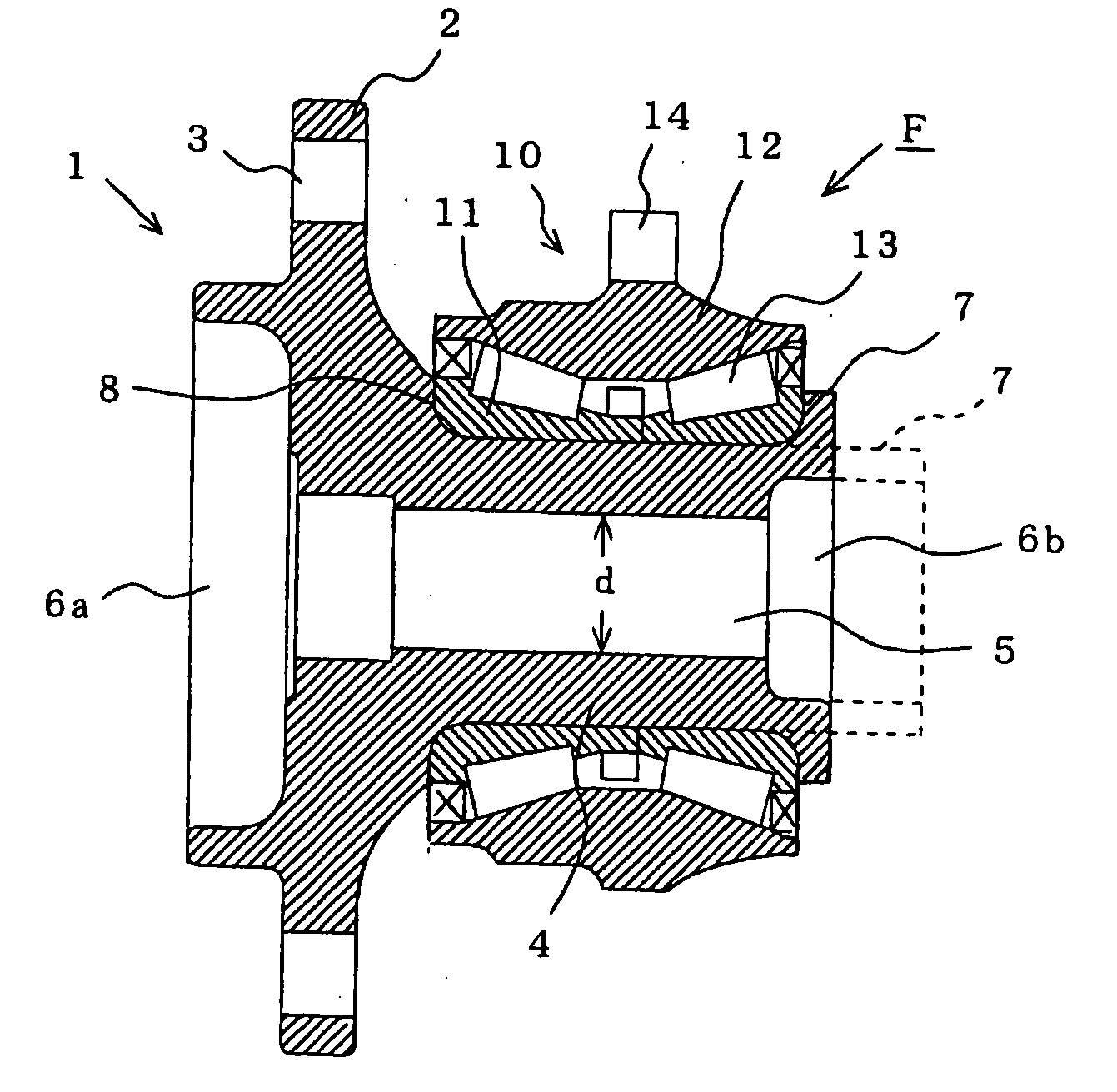
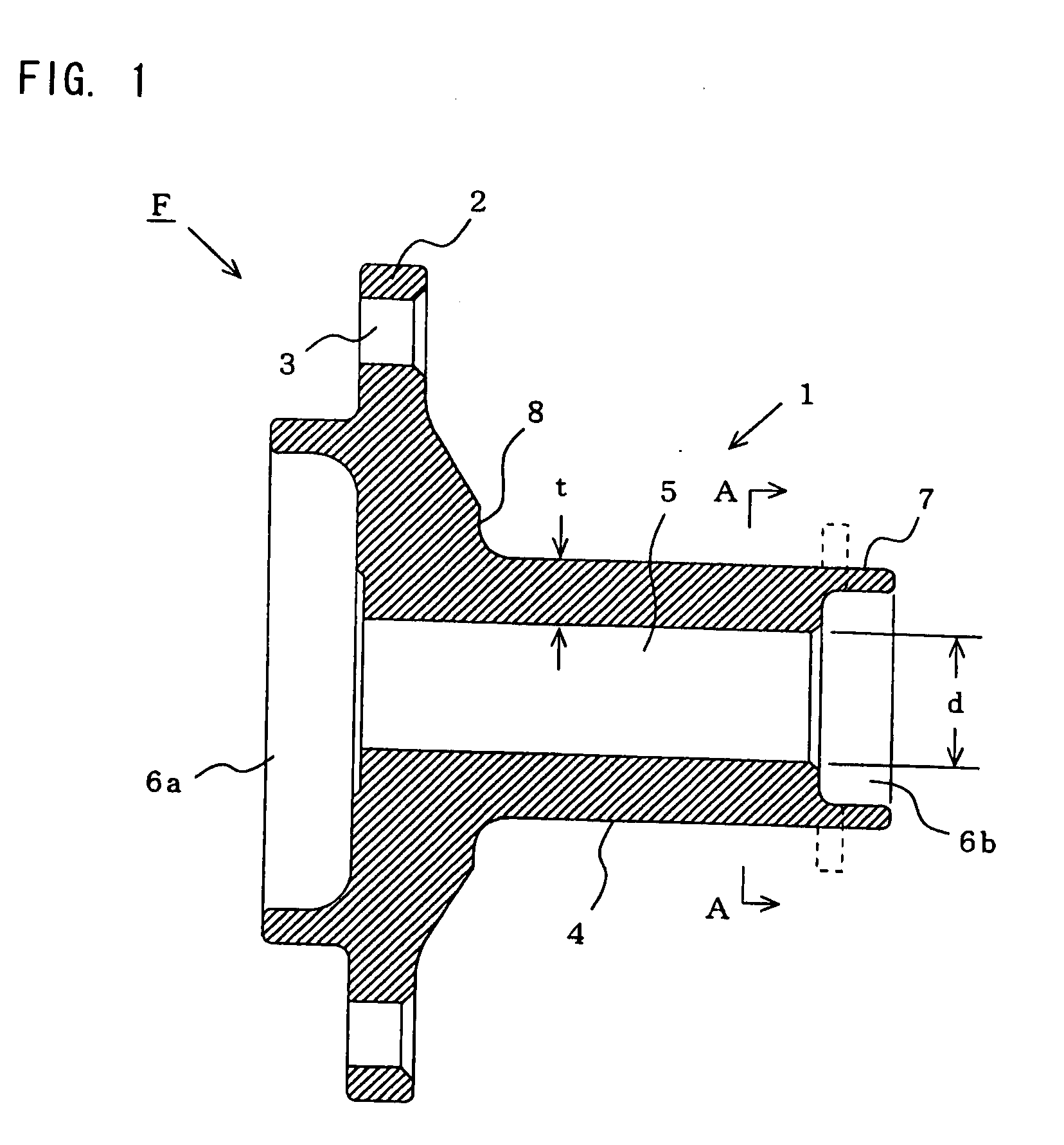
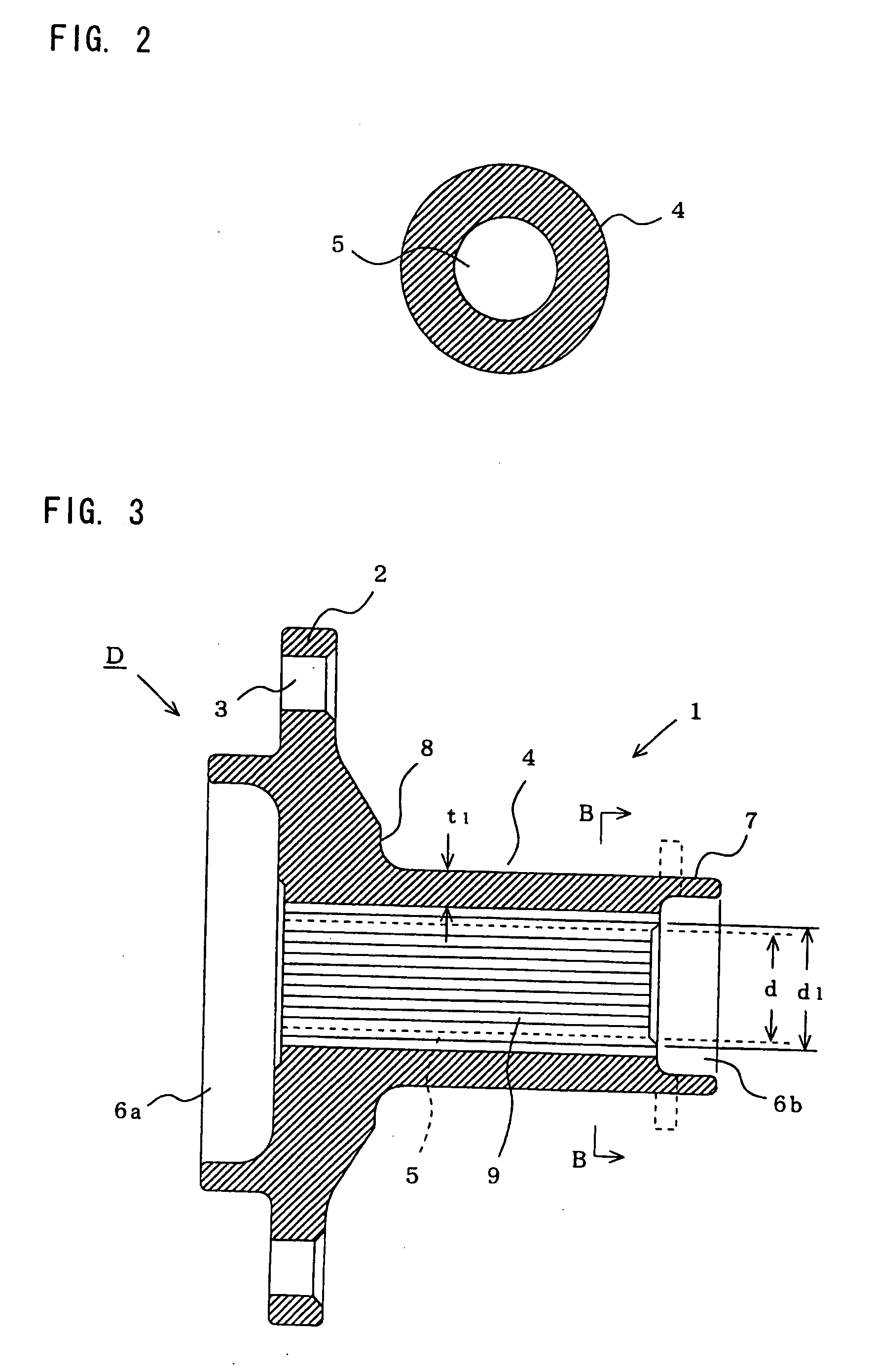
[0027]FIG. 1 is a vertical cross-sectional view of a hub shaft which is a main portion of a driven wheel bearing apparatus forming a preferred embodiment of an axle bearing apparatus of the present invention, FIG. 2 is a cross-sectional view taken along the line A-A of FIG. 1, FIG. 3 is a vertical cross-sectional view of a hub shaft which is a main portion of a driving wheel bearing apparatus forming a preferred embodiment of an axle bearing apparatus of the invention, and FIG. 4 is a cross-sectional view taken along the line B-B of FIG. 3. Those portions identical to the corresponding portions of the conventional structures of FIGS. 5 and 6 will be designated by identical reference numerals, respectively, and part of description thereof will be omitted.

[0028]A material for each of the hub shafts 1 of the driving and driven wheel bearing apparatuses D and F (the axle bearing apparatus of the invention) is formed into a predetermined shape, for example, by forging, and a through hole...


PUM


Abstract

An axle bearing apparatus includes a hub shaft for common use with a driving wheel bearing apparatus and a driven wheel bearing apparatus, the hub shaft including an axle-mounting flange formed at its outer end portion, and a cylindrical portion formed at an inner side of the flange and having a through hole formed in a center portion of the cylindrical portion, and a bearing portion press-fitted on the cylindrical portion of the hub shaft and including an inner ring, an outer ring and rolling elements disposed between the inner and outer rings. The hub shaft is used for the driven wheel bearing apparatus, and alternatively the through hole in the hub shaft is enlarged in diameter, and a spline are formed axially in an inner surface of the diameter-enlarged through hole, and the hub shaft thus processed is used for the driving wheel bearing apparatus.

Description

BACKGROUND OF THE INVENTION[0001]This invention relates to an axle bearing apparatus, for example, of an automobile, and more particularly to an axle bearing apparatus for common use with a hub shaft of a driving wheel bearing apparatus and a hub shaft of a driven wheel bearing apparatus, and a method of producing the hub shaft for the driving wheel bearing apparatus.[0002]For example, a hub shaft of a driving wheel bearing apparatus for an automobile and a hub shaft of a driven wheel bearing apparatus have heretofore been provided separately from each other (see, for example, JP-A-2002-206538 and JP-A-2003-54210). Recently, however, in order to reduce costs, there has been developed the type of bearing apparatus for common use with a hub shaft of a driving wheel bearing apparatus and a hub shaft of a driven wheel bearing apparatus.[0003]FIG. 5 is a cross-sectional view of a conventional driven wheel bearing apparatus for common use with a hub shaft of a driving wheel bearing appara...

Claims


Application Information

Patent Timeline
IPC IPC(8): B60B37/00F16C17/00
CPCB60B27/00F16C35/063F16C19/386F16C2326/02
Inventor INOUE, SHIGERUHARADA, TAKUMIKOMA, YUTAKA
Owner JTEKT CORP
Why Eureka
Try Eureka