Image forming apparatus

a technology of image forming apparatus and air blowoff, which is applied in the direction of optics, instruments, electrographic processes, etc., can solve the problems of rising temperature of the developing device that supplies toner, and melting of toner, so as to secure the air blowoff portion to the housing or the like with eas

a technology of image forming apparatus and air blowoff, which is applied in the direction of optics, instruments, electrographic processes, etc., can solve the problems of rising temperature of the developing device that supplies toner, and melting of toner, so as to secure the air blowoff portion to the housing or the like with eas

US20080279580A1Inactive Publication Date: 2008-11-13KYOCERA DOCUMENT SOLUTIONS INC

Image

  • Image forming apparatus
  • Image forming apparatus
  • Image forming apparatus

Examples


Embodiment Construction

[0052]Hereinafter, an embodiment of the present invention will be described with reference to the accompanying drawings. It is to be understood that the present invention is not limited in any way by the embodiment thereof described below, because this embodiment is merely an example of how the invention can be preferably implemented. In addition, the application of the invention and the terms or the like used in the present specification are not limited to those specifically described below.

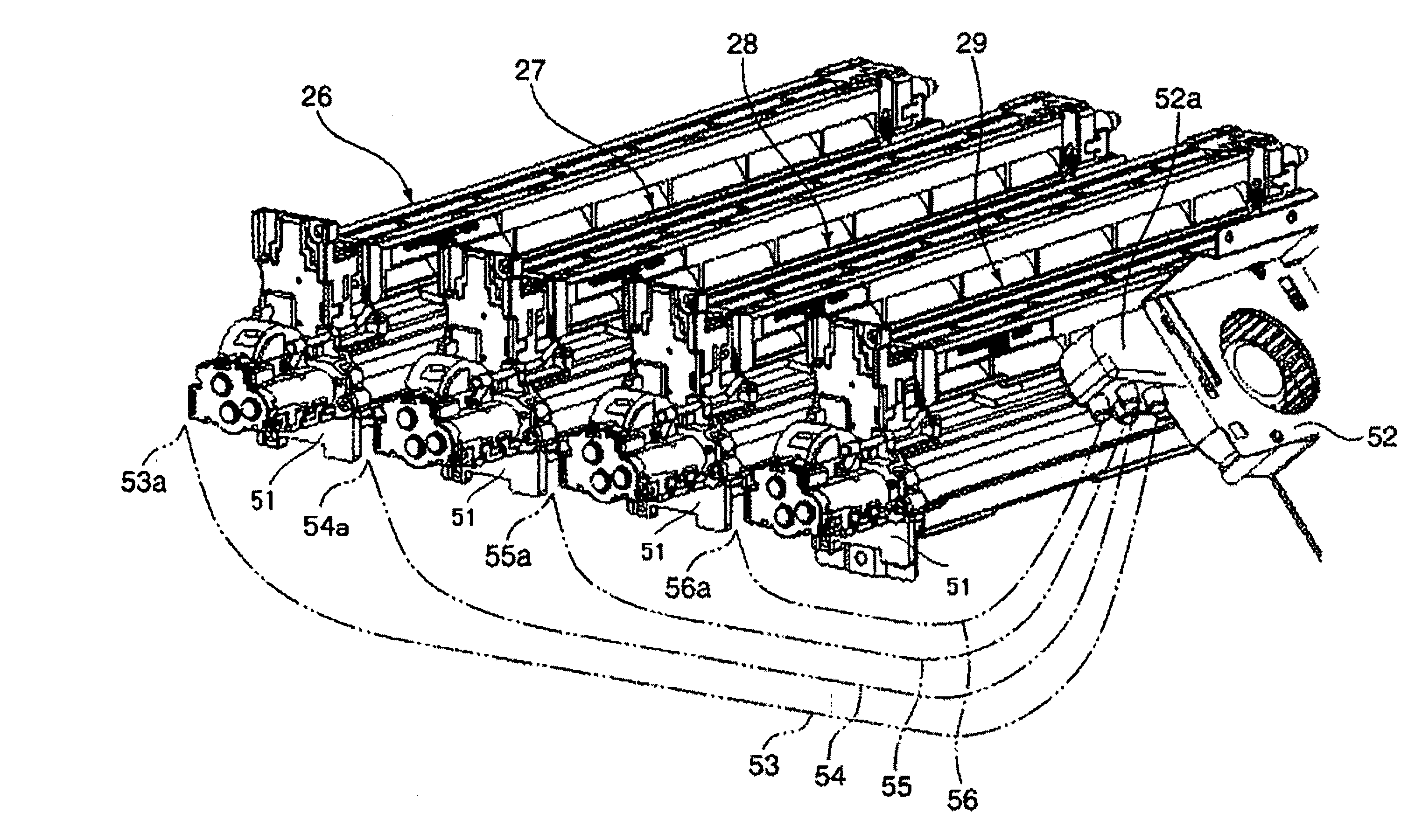
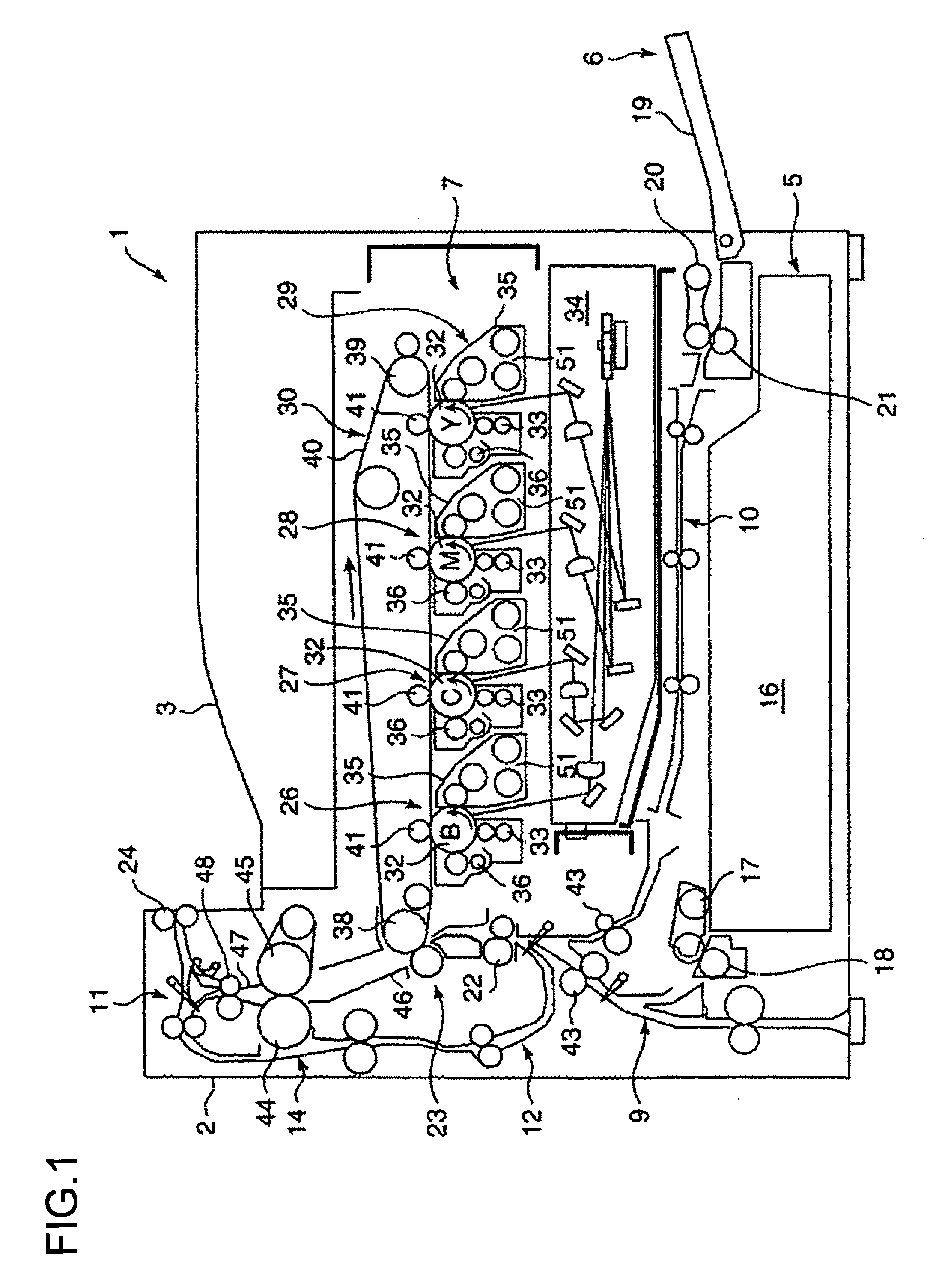
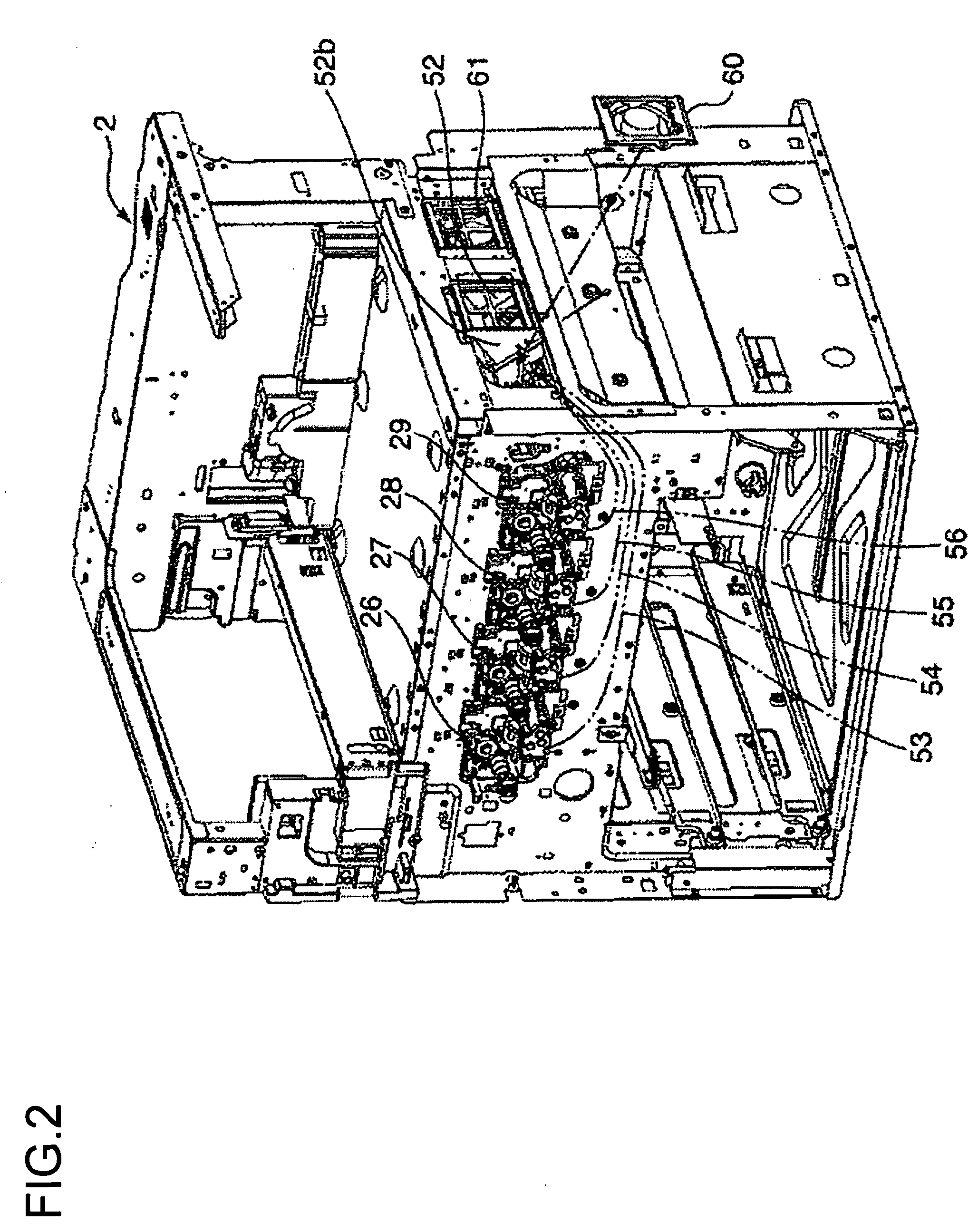
[0053]FIG. 1 is a diagram schematically showing the internal structure of an image forming apparatus 1 according to the embodiment of the invention. The image forming apparatus 1 is a tandem-type color printer, and includes a box-shaped housing 2 (hereinafter an “apparatus body 2”) inside which a color image is formed on paper. The apparatus body 2 has, on the top face thereof, a paper ejecting portion 3 into which the paper on which the color image is formed is ejected.

[0054]Inside the apparatu...


PUM


Abstract

An image forming apparatus has: a housing; a member to be cooled provided inside the housing, the member to be cooled in which heat builds up; an airflow producing portion provided in a predetermined position of the housing for taking in air outside the housing; an air guide member for passing the air thus taken in through a hollow cross-section part, and guiding the air to the member to be cooled to cool the member to be cooled; an air inlet portion provided at one end of the air guide member for taking in the air from the airflow producing portion; and an air blowoff portion provided at another end of the air guide member for sending the air to the member to be cooled, the air blowoff portion in which the cross-sectional area of the hollow cross-section part is smaller than the cross-sectional area of the hollow cross-section part in the air inlet portion.

Description

[0001]This application is based on Japanese Patent Application No. 2007-125181 filed on May 10, 2007, the contents of which are hereby incorporated by reference.BACKGROUND OF THE INVENTION[0002]1. Field of the Invention[0003]The present invention relates to image forming apparatuses using an electrophotographic process, such as copiers, printers, and facsimiles. More particularly, the present invention relates to an image forming apparatus that can cool a member to be cooled disposed inside the apparatus with an airflow producing portion (cooling fan).[0004]2. Description of Related Art[0005]In image forming apparatuses such as copiers and printers, a heated roller fusing method is widely adopted as a method for fusing an unfused toner image to paper. In the heated roller fusing method, at least one of a pair of rollers forming a nip has a built-in heat source, and paper carrying an unfused toner image is passed through the nip formed between the pair of rollers heated by the heat s...

Claims


Application Information

Patent Timeline
13 Nov 2008
Publication
US20080279580A1
IPC
G03G21/20
CPC
G03G2221/1645; G03G21/206
Inventors
GODA, MITSUHIRO