

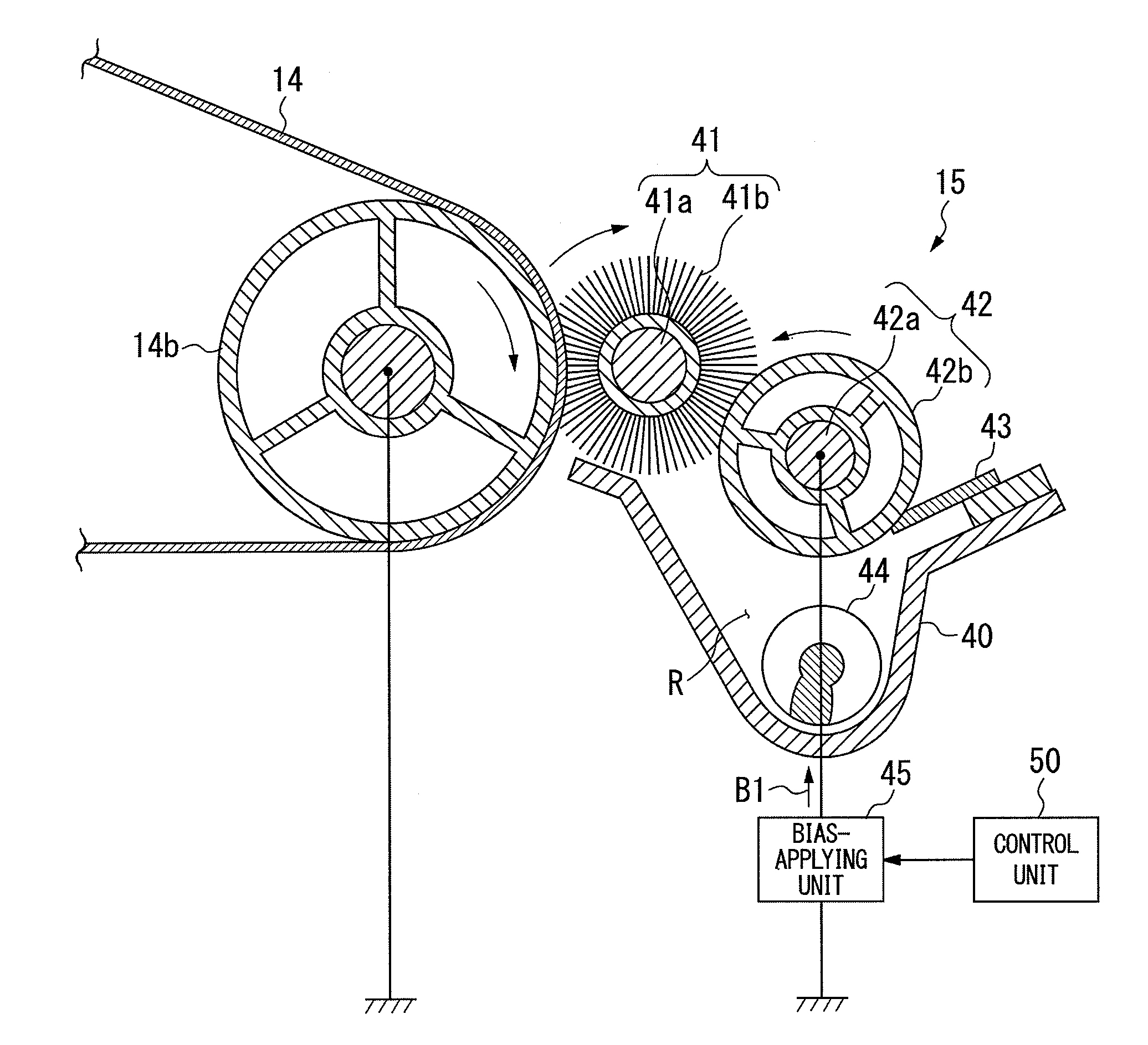
Image-forming apparatus with a bias applying unit for switching between a first bias for removing residual toner and a second bias for expelling residual toner
a technology of applying unit and image-forming apparatus, which is applied in the direction of electrographic process apparatus, optics, instruments, etc., can solve the problems of increasing the drive load the danger of damaging the surface of the transfer member, and the quality of image-forming, so as to improve the cost or the size of the apparatus, the effect of simple control
- Summary
- Abstract
- Description
- Claims
- Application Information
AI Technical Summary
Benefits of technology
Problems solved by technology
Method used
Image

Examples
Embodiment Construction
[0019]An image-forming apparatus according to an embodiment of the present disclosure is described in detail with reference to the drawings. While the following explanation describes a color printer as an example of an image-forming apparatus, the present disclosure can also be applied in a black-and-white printer, and in an image-forming apparatus other than a printer, such as a copier, a facsimile, and a complex device.
Overall Configuration of Image-Forming Apparatus
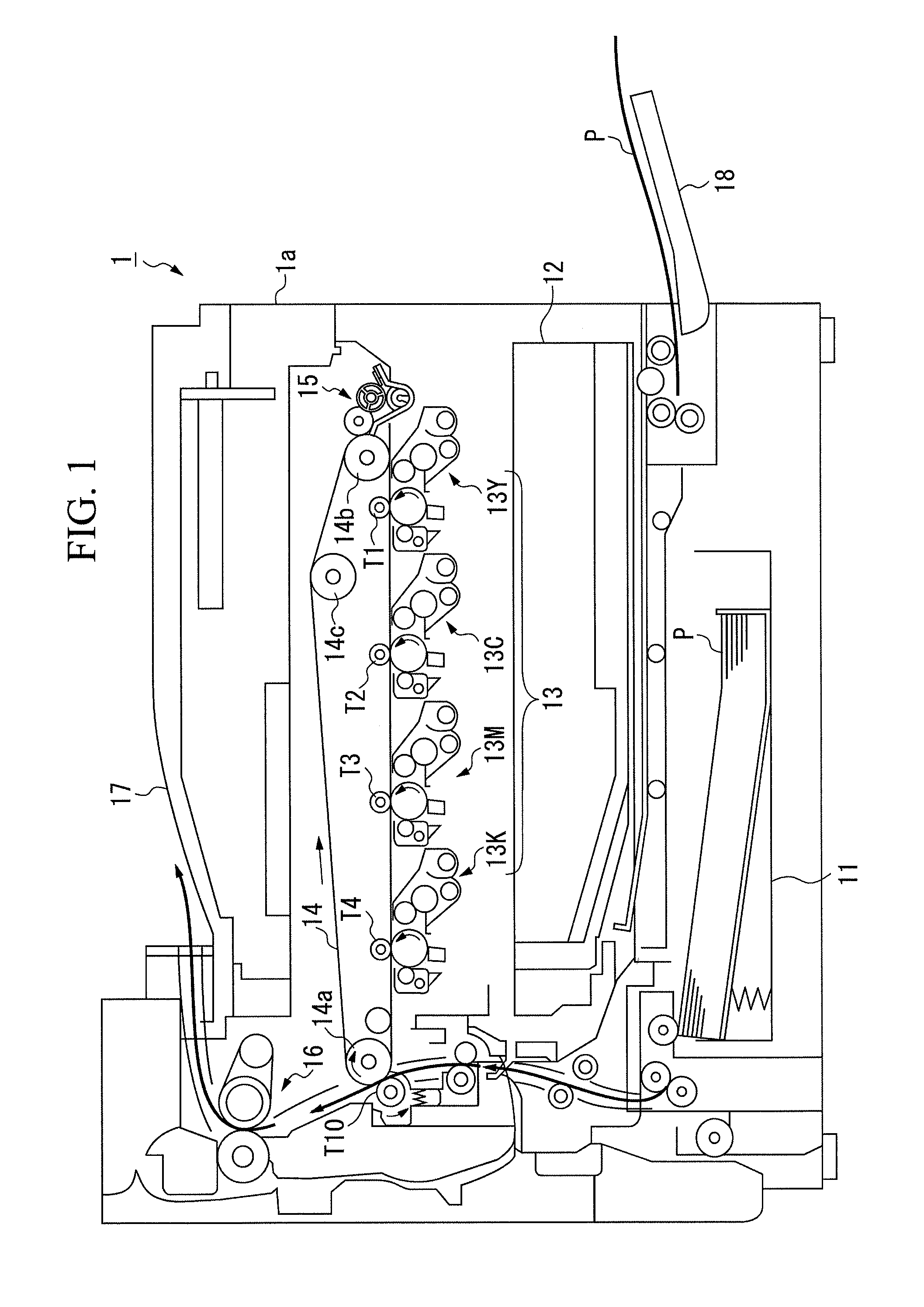
[0020]FIG. 1 is a cross-sectional diagram showing the configuration of a color printer as an image-forming apparatus according to an embodiment of the present disclosure. As shown in FIG. 1, a color printer 1 includes a paper-feeding cassette 11, a laser scanner unit (LSU) 12, an image-forming unit 13, an intermediate transfer belt 14 (image carrier), a cleaning device 15, a fusing device 16, and the like, inside a box-shaped apparatus body 1a, and prints, for example, an image corresponding to printing data input from...
PUM
 Abstract
Description
Claims
Application Information