Method for Receiving a Medical Element in a Manipulation Apparatus, a Manipulation

a technology of manipulating apparatus and medical element, which is applied in the field of manipulating apparatus and receiving medical element, can solve the problem of tight space available for manipulating apparatus, and achieve the effect of improving the patient's comfort and comfor

a technology of manipulating apparatus and medical element, which is applied in the field of manipulating apparatus and receiving medical element, can solve the problem of tight space available for manipulating apparatus, and achieve the effect of improving the patient's comfort and comfor

US20080280253A1Inactive Publication Date: 2008-11-13HERAEUS KULZER

Image

  • Method for Receiving a Medical Element in a Manipulation Apparatus, a Manipulation
  • Method for Receiving a Medical Element in a Manipulation Apparatus, a Manipulation
  • Method for Receiving a Medical Element in a Manipulation Apparatus, a Manipulation

Examples


Embodiment Construction

[0020]The invention is now explained in closer detail by reference to embodiments, wherein the figures show in combination with a medical element in accordance with the invention:

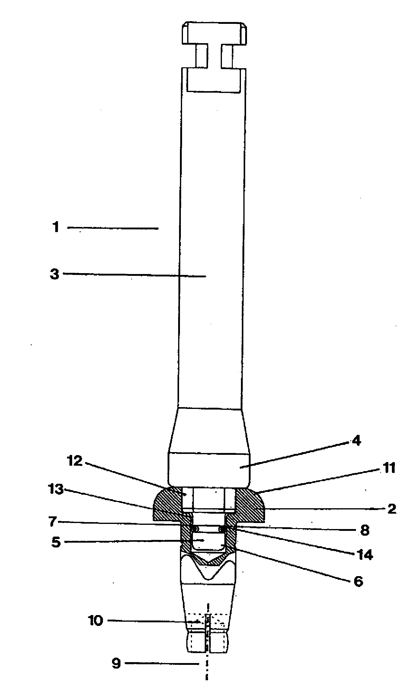
[0021]FIG. 1 shows a first;

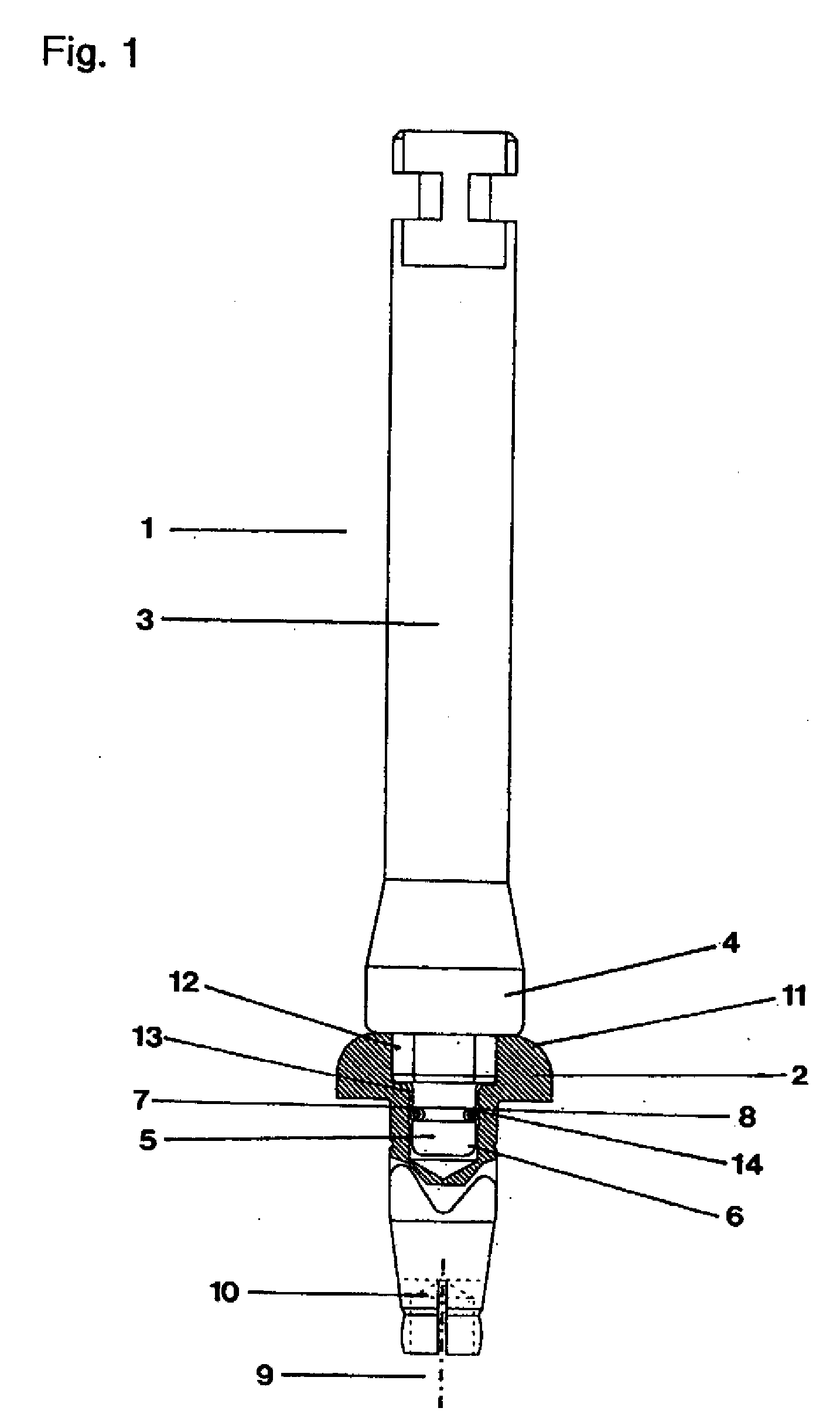
[0022]FIG. 2 shows a second, and

[0023]FIG. 3 shows a third manipulation apparatus in accordance with the invention.

[0024]The manipulation apparatus 1 in accordance with the invention as shown in FIG. 1 is an insertion tool or “insertion post” for use with a rotatable tool holder (the so-called dentist's drill) which is not shown, is usually driven pneumatically and by means of which a medical element 2, which is a healing cap, can be received.

[0025]The manipulation apparatus 1 is made of special steel and has a cylindrical oblong basic body 3 which starts out from a standardized connecting bracket (the so-called “elbow bracket”) and which after a slight bulging section 4 ends in a clearly narrower pin-like receiving element 5 as compared with the basic body 3. The receiving elemen...


PUM


Abstract

A method is disclosed for receiving a medical element in a manipulation apparatus in such a way that it can be inserted in an implant or be removed therefrom and the medical element is secured against longitudinal displacement by means of clip element, whereby a security element is introduced into the clip element such that the clip element is spread or blocked perpendicular to the longitudinal axis.

Description

[0001]The invention relates at first to a method for receiving a medical element in a manipulation apparatus, with the medical element being received by means of a receiving element in such a way that it can be inserted in an implant by means of a manipulation apparatus having the receiving element or can be removed from the implant, with the receiving element being introduced into the receiving recess in a longitudinal direction of a receiving recess of the medical element and being secured in the receiving recess by means of a clip element against displacement in the longitudinal direction. The invention further relates to a manipulation apparatus for a medical element, comprising a receiving element by means of which the medical element can be received for insertion into an implant or for removal from the implant, with the receiving element being introducible into a receiving recess of the medical element in a longitudinal direction of the receiving recess and being securable by ...

Claims


Application Information

Patent Timeline
13 Nov 2008
Publication
US20080280253A1
IPC
A61C3/00
CPC
A61B17/8888; A61C8/0089; A61C8/008
Inventors
AUGTHUN, MICHAEL; BOSCHEMEYER, THOMAS