Chain tensioner

a tensioner and chain technology, applied in the direction of belts/chains/gearings, mechanical instruments, belts/chains/gearings, etc., can solve the problems of reducing the damper effect of hydraulic fluid, unable to effectively absorb chain vibration, and unable to smoothly discharge air in the pressure chamber through the helical gap between internal and external threads, so as to achieve smooth guided into the air passage

Inactive Publication Date: 2008-11-13
NTN CORP
View PDF4 Cites 44 Cited by
  • Summary
  • Abstract
  • Description
  • Claims
  • Application Information

AI Technical Summary

Benefits of technology

[0022]In a still another arrangement, the cylindrical portion of the valve seat has in its upper portion such an air passage. With this arrangement, it is possible to reliably guide air in the cylindrical portion into the portion of the cylinder chamber near the closed end thereof, irrespective of the rotational position of the screw rod.
[0023]When such an air passage is formed in the screw rod or

Problems solved by technology

If air enters the pressure chamber, when the tension of the chain increases and the plunger is pushed in, because the plunger compresses air, the hydraulic damper effect decreases, so that it is impossible to effectively absorb vibration of the chain.
Therefore, it is impossible

Method used


Image

  • Chain tensioner
  • Chain tensioner
  • Chain tensioner

Examples


Embodiment Construction

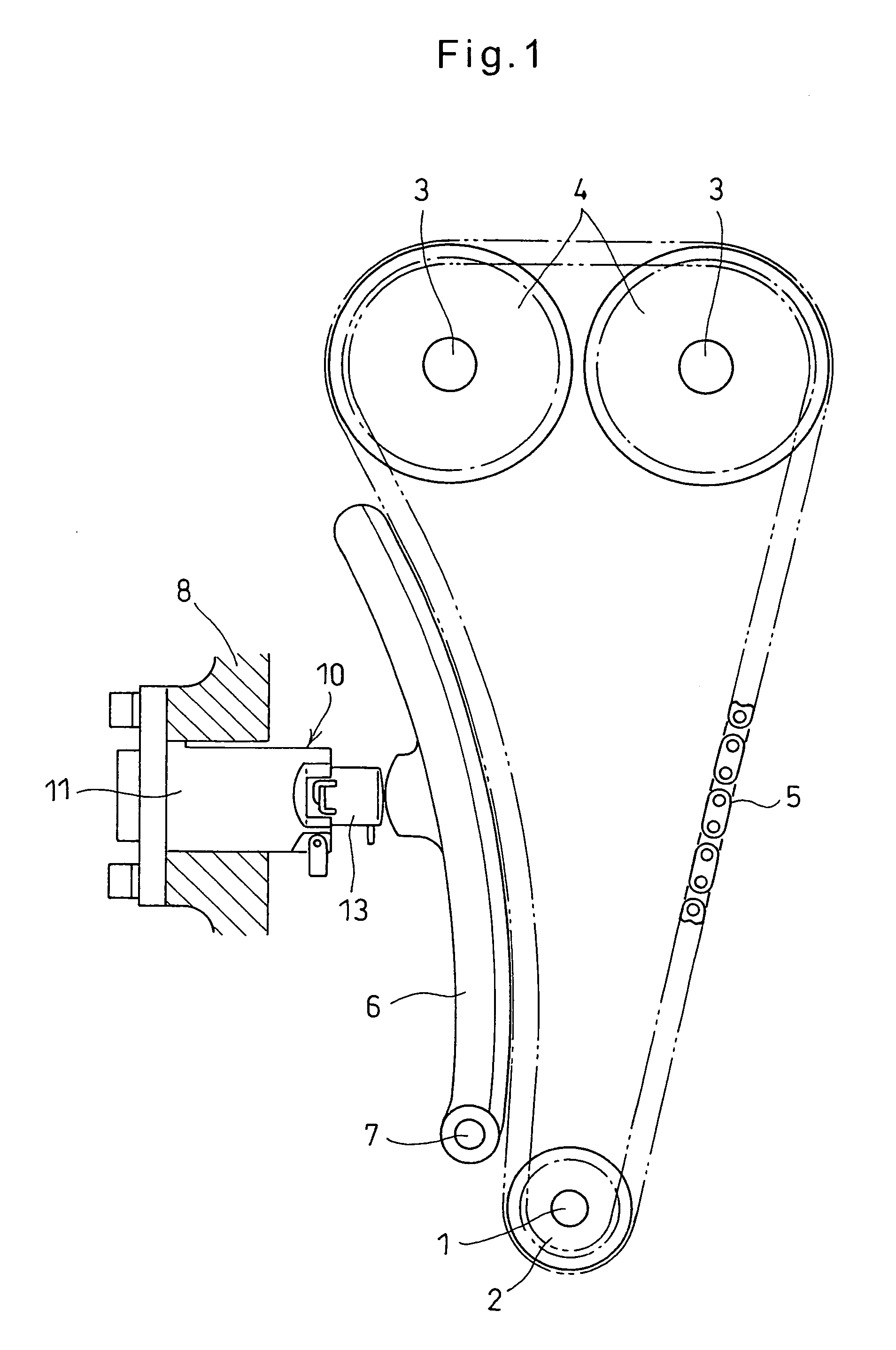
[0036]Now the embodiments of this invention are described with reference to the drawings. FIG. 1 shows a chain tension adjusting device. As shown, a chain 5 is trained about a sprocket 2 mounted to one end of a crankshaft 1, and sprockets 4 each mounted to one end of one of camshafts 3.

[0037]A chain guide 6 is provided to extend along a slack side of the chain 5. The chain guide 6 is pivotable about a shaft 7. An adjusting force is applied from a chain tensioner 10 to the chain 5 through the chain guide 6.

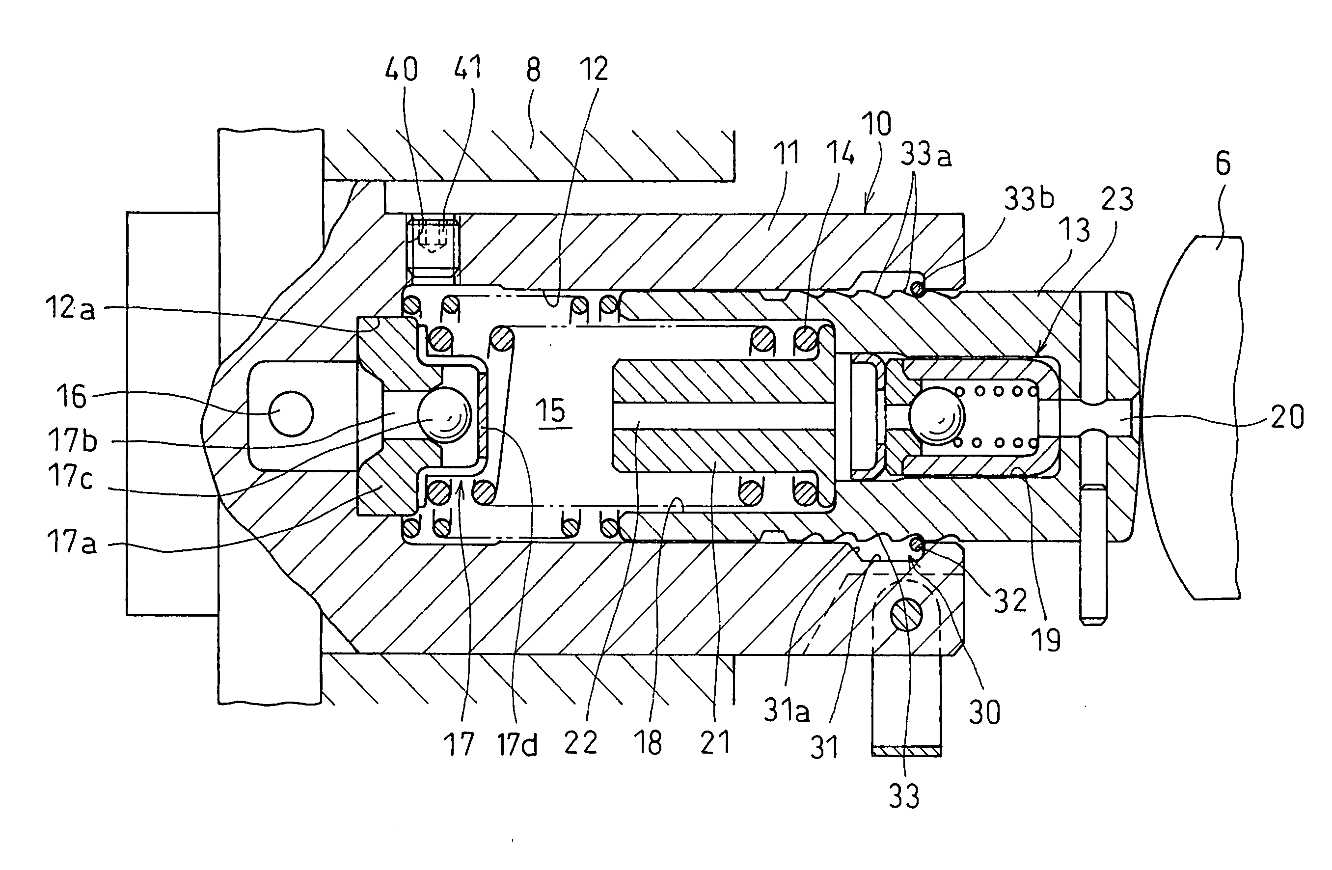
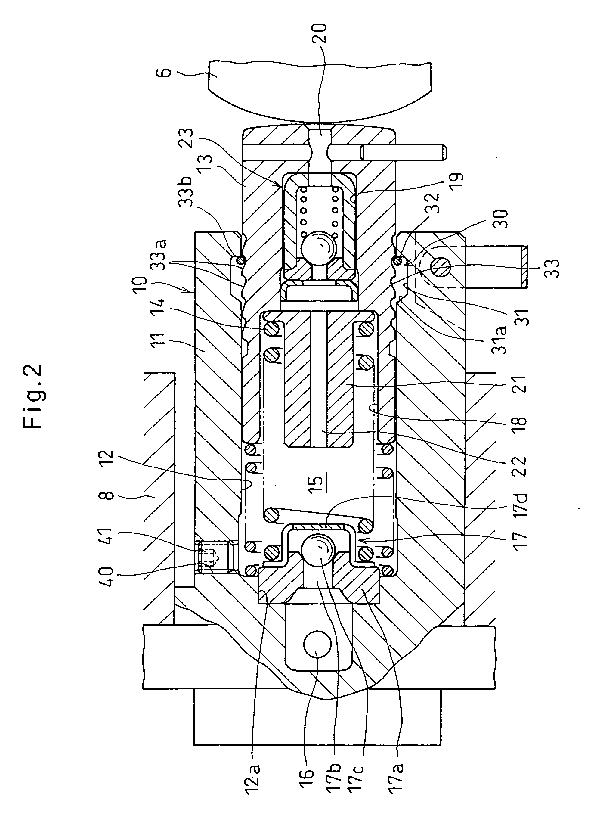
[0038]As shown in FIG. 2, the chain tensioner 10 includes a housing 11 configured to be mounted to an engine cover 8. The housing 11 defines a cylinder chamber 12 having a closed end. In the cylinder chamber 12, a plunger 13 and a return spring 14 are mounted. The return spring 14 biases the plunger 13 outwardly of the cylinder chamber.

[0039]The plunger 13 defines therebehind a pressure chamber 15 in the housing 11. The housing 11 is formed with an oil supply passage 16 communicati...


PUM


Abstract

A chain tensioner includes a housing defining a cylinder chamber. A plunger is mounted in the cylinder chamber so as to be slidable along an inner surface of the cylinder chamber. A return spring is mounted in the cylinder chamber to bias the plunger outwardly. The housing is formed with an oil supply passage communicating with a pressure chamber defined in the housing behind the plunger. A check valve is disposed at an oil exit of the oil supply passage and configured to close the oil supply passage when the pressure in the pressure chamber is higher than the pressure in the oil supply passage. The housing is formed with a threaded hole extending from an upper portion of an outer periphery of the housing to the pressure chamber. A screw has its external thread in threaded engagement with the internal thread of the threaded hole, whereby a gap, as an air bleed passage, is defined between the internal and external threads. The internal thread of the threaded hole has an internal diameter larger than an internal diameter of an internal thread under JIS.

Description

BACKGROUND OF THE INVENTION[0001]The present invention relates to a chain tensioner for keeping constant the tension of a timing chain or a timing belt for driving camshafts.[0002]Typically, a chain transmission device for transmitting the rotation of a crankshaft to camshafts through a timing chain or a timing belt (hereinafter simply referred to as the “chain”) includes a chain tensioner for applying an adjusting force to the slack side of the chain, thereby keeping constant the tension of the chain.[0003]Such a chain tensioner is disclosed in JP Patent 3585655. This chain tensioner includes a housing defining a cylinder chamber, a plunger mounted in the cylinder chamber, and a return spring also mounted in the cylinder chamber and biasing the plunger outwardly of the cylinder chamber. The housing is formed with an oil supply passage communicating with a pressure chamber defined in the housing behind the plunger. The pushing force applied to the plunger is damped by oil supplied i...

Claims


Application Information

Patent Timeline
IPC IPC(8): F16H7/08
CPCF16H7/0836F16H7/0848F16H2007/0806F16H2007/0814
Inventor RYOUNO, YOSHIAKISATO, SEIJIKITANO, SATOSHIONIMARU, KOUICHINAKAO, GORO
Owner NTN CORP
Why Eureka
Try Eureka