Methods for optimizing parameters of gas turbine engine components

Active Publication Date: 2008-11-13
GENERAL ELECTRIC CO
View PDF2 Cites 21 Cited by
  • Summary
  • Abstract
  • Description
  • Claims
  • Application Information

AI Technical Summary

Problems solved by technology

Such temperatures can place the engine, its various modulated systems, and parts thereof, under tremendous thermal stress, which can lead to fatigue, wear, and in some instances, failure.
Internal and external fluid velocities of gas turbine engines can impact both individual parts as well as overall system efficiency.
However, measuring fluid flow in components having complex internal passages is often complicated by the fact that such devices typically have multiple regions of flow separation and strong secondary flows.
However, this large number of instruments can lead to technical problems such as fluid flow blockage due to the intrusiveness of the instruments.
Unfortunately, the computer resource requirements and the fidelity of boundary conditions needed to quantify the 3D fluid flow through a complex passage can often be limiting factors.
Other flow measuring systems currentl

Method used


Image

  • Methods for optimizing parameters of gas turbine engine components
  • Methods for optimizing parameters of gas turbine engine components
  • Methods for optimizing parameters of gas turbine engine components

Examples


Embodiment Construction

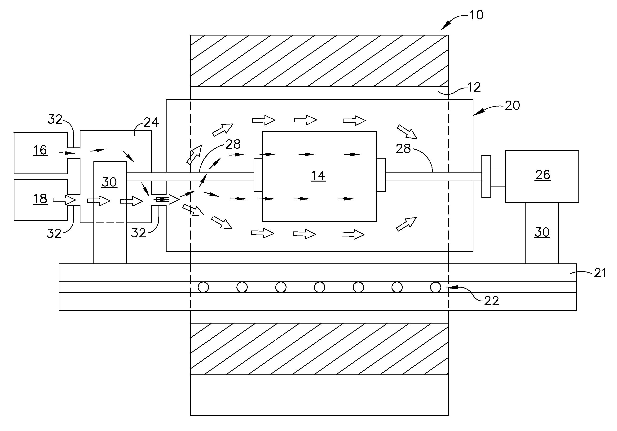
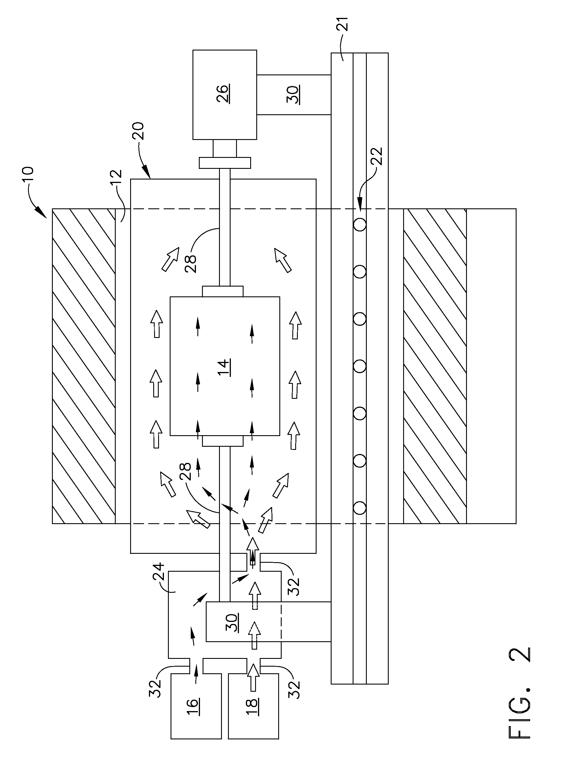
[0017]Embodiments described herein generally relate to methods for optimizing fluid flow in gas turbine engines, modulated engine systems and parts thereof. In general, such methods may involve optimizing at least one parameter of an engine component using an experimentally measured 3D flow field by providing a magnetic resonance imaging machine, providing a model of a component, which may have at least one rotatable part, placing the model into the magnetic resonance imaging machine with a fluid flow source for applying an external fluid flow and / or and internal fluid flow, applying the fluid flow to the model, collecting data related to the fluid flow about the model, and optimizing at least one operating parameter of the component using the data.

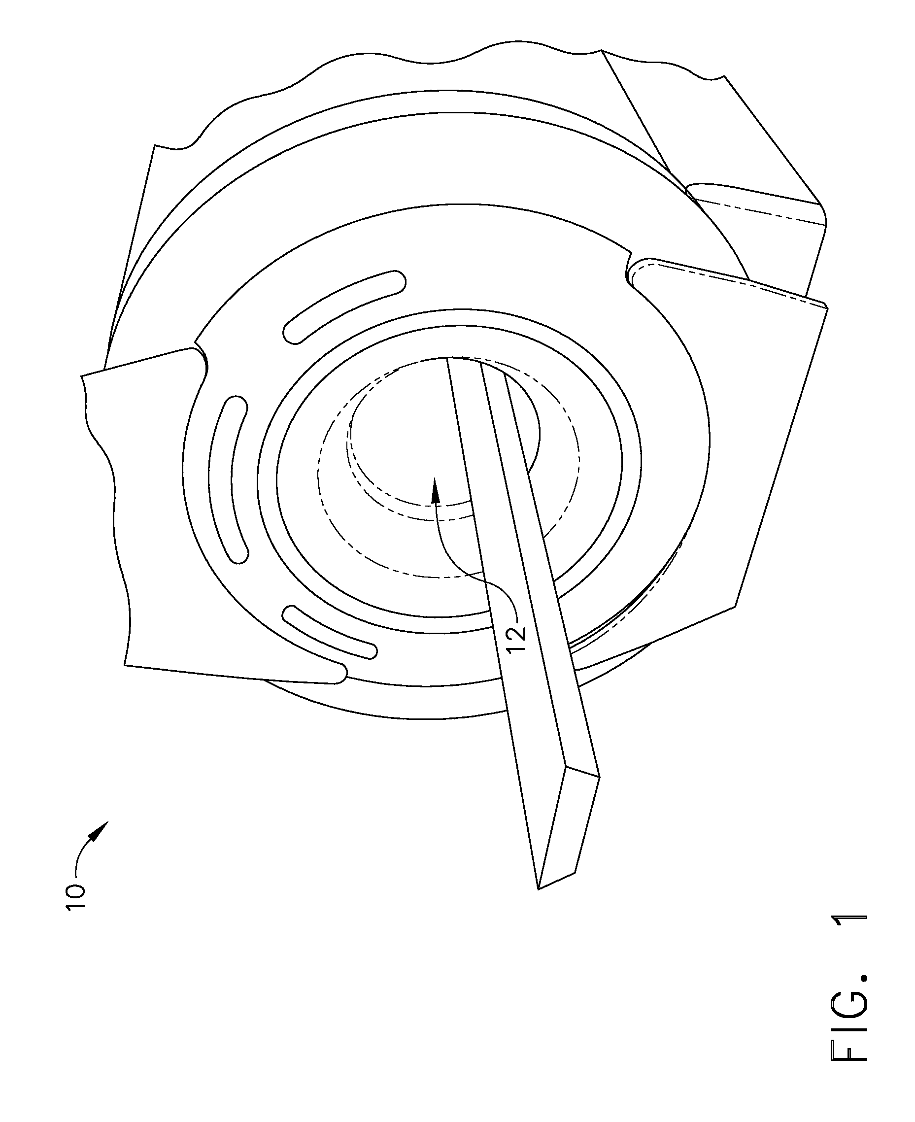
[0018]The methods set forth herein initially involve providing a magnetic resonance imaging (MRI) machine 10, as shown generally in FIG. 1. Any conventional MRI machine may be used herein, however, one example is the 1.5T GE Signa® CV / I M...


PUM


Abstract

Methods for optimizing at least one operating parameter of an engine component using an experimentally measured 3D flow field involving providing a magnetic resonance imaging machine, providing a model of an engine component, placing the model into the magnetic resonance imaging machine with a fluid flow source for applying an external fluid flow, applying the external fluid flow to the model, collecting data related to the external fluid flow about the model, and optimizing at least one operating parameter of the component using the data.

Description

TECHNICAL FIELD[0001]Embodiments described herein generally relate to methods for optimizing at least one operating parameter of an engine component. More particularly, embodiments herein generally describe methods for optimizing at least one operating parameter of an engine component using an experimentally measured 3D fluid flow field generated by a magnetic resonance imaging machine.BACKGROUND OF THE INVENTION[0002]Gas turbine engines, such as those utilized in aircrafts, operate at high temperatures to maximize efficiency and thrust. Such temperatures can place the engine, its various modulated systems, and parts thereof, under tremendous thermal stress, which can lead to fatigue, wear, and in some instances, failure.[0003]Internal and external fluid velocities of gas turbine engines can impact both individual parts as well as overall system efficiency. However, measuring fluid flow in components having complex internal passages is often complicated by the fact that such devices...

Claims


Application Information

Patent Timeline
IPC IPC(8): G06F17/50G06G7/64G06G7/57G06G7/72
CPCG01M9/065B33Y80/00
Inventor CHOU, CHEN-YU JACKLEE, CHING-PANGWISLER, DAVID CHARLES
Owner GENERAL ELECTRIC CO
Why Eureka
Try Eureka