Method and apparatus for controlling cache

Inactive Publication Date: 2008-11-13
FUJITSU LTD
View PDF1 Cites 58 Cited by
  • Summary
  • Abstract
  • Description
  • Claims
  • Application Information

AI Technical Summary

Benefits of technology

[0010]It is an object of the present invention to at least

Problems solved by technology

Accesses to a specific block, which are the storage unit in the cache memory, may frequently fail due to a memory failure.
Although the block that causes the failure can be easily degraded by the degradation m

Method used


Image

  • Method and apparatus for controlling cache
  • Method and apparatus for controlling cache
  • Method and apparatus for controlling cache

Examples


Embodiment Construction

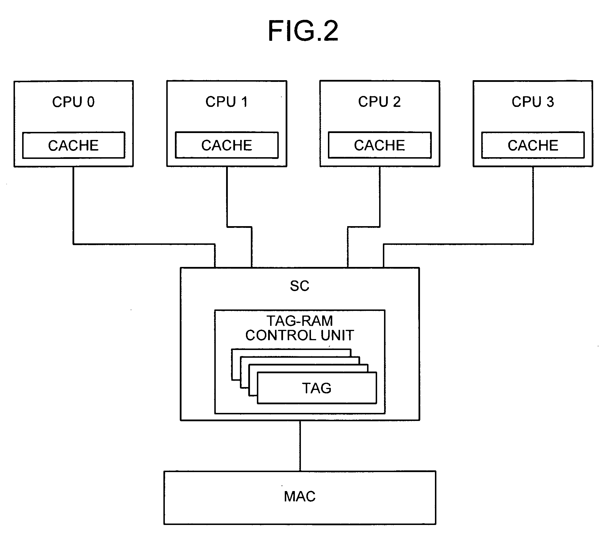
[0021]Exemplary embodiments of the present invention are described in detail below with reference to the accompanying drawings. In a present embodiment of the present invention, a tag-RAM control unit of a system controller (SC) uses a predetermined method to control a plurality of tag RAMs in CPUs. The SC and the CPUs are connected to each other.

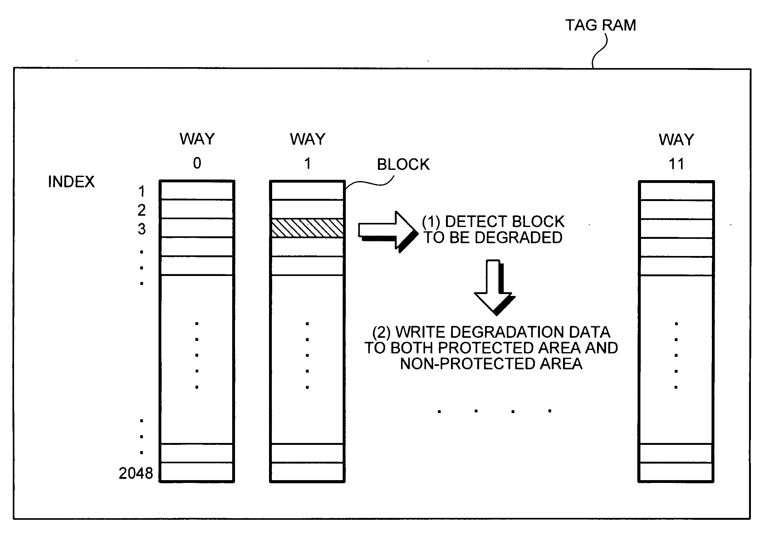
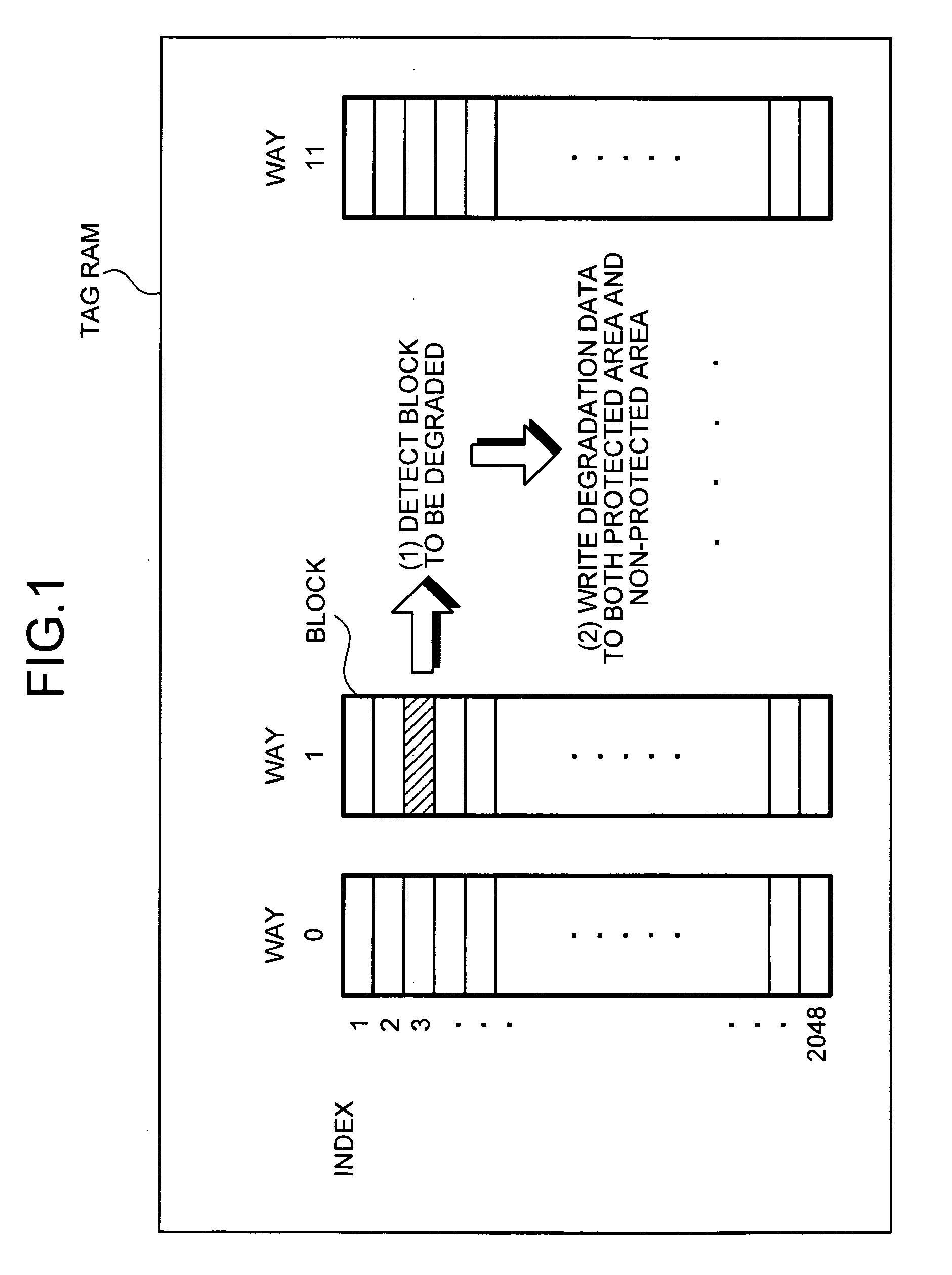
[0022]FIG. 1 is a schematic diagram for explaining an overview of a cache control method according to the present embodiment. More particularly, FIG. 1 is a schematic diagram of data structure of a tag RAM. The tag RAM shown in FIG. 1 is for a single CPU. If, for example, there are four CPUs, four sets (for four CPUs) of the tag RAM shown in FIG. 1 are used.

[0023]The tag RAM includes total 12 ways from a way 0 to a way 11. Each way includes 2048 blocks. The block is a unit of entry data. The CPU collectively accesses a group of blocks in different ways having the same index, i.e., blocks within the same cache line. For example, if the targe...


PUM


Abstract

A cache controller controls at least one cache. The cache includes ways including a plurality of blocks that stores therein entry data. A writing unit writes degradation data to a failed block. The degradation data indicates that the failed block is in a degradation state. A reading unit reads entry data from a block. A determining unit determines, if the entry data obtained by the reading unit includes the degradation data, that the block is in the degradation state.

Description

BACKGROUND OF THE INVENTION[0001]1. Field of the Invention[0002]The present invention relates to a technology for controlling a cache that includes ways including a plurality of blocks that store therein entry data, and more particularly, to a technology for controlling block degradation.[0003]2. Description of the Related Art[0004]Cache memories are low-capacity and high-speed memories that are widely used to solve problems caused by difference in performance between a processor such as a central processing unit (CPU) and a storage device such as a memory. The cache memory includes a plurality of ways arranged in parallel. Each of the ways includes a plurality of storage units called “block” as many as indices of the cache memory. A group of blocks in different ways having the same index (i.e., blocks within the same cache line) is usually accessed simultaneously.[0005]Tag random access memories (tag RAMs) are used to store therein tags indicative of addresses where cache data, whi...

Claims


Application Information

Patent Timeline
IPC IPC(8): G06F12/00
CPCG06F11/1064G06F12/0846G06F12/0864
Inventor KUSACHI, SOUTAMORITA, KUNIKIUKAI, MASAKIOKAWA, TOMOYUKI
Owner FUJITSU LTD
Why Eureka
Try Eureka