Pipe clip

a technology of pipe clips and clips, applied in the field of pipe clips, can solve the problems of reducing the fitting time and often attaching pipes under difficult circumstances, and achieve the effect of facilitating movement, effective tightening of the clip around the pipe, and convenient closing

Inactive Publication Date: 2008-11-20
J VAN WALRAVEN
View PDF8 Cites 9 Cited by
  • Summary
  • Abstract
  • Description
  • Claims
  • Application Information

AI Technical Summary

Benefits of technology

[0006]During closing of the pipe clip, the head of the tightening element is pressed against the pivotable arresting plate. As a result, the tightening element pivots outward but, in addition, the arresting plate pivots upward, allowing the head of the tightening element to move more easily along the edge of the arresting plate and the shank of the tightening element to be received more easily in the recess in the arresting plate. The pipe is often attached under difficult circumstances, for example when a fitter is standing on a ladder, in a plurality of pipe clips suspended in line with one another. During closing, the weight of the pipe can press at least partially against the bottom clip half. In the case of the pipe clip according to the invention, it has been found that, as a result of the combination of the pivotable female fastening element with the tightening element and the pivotable arresting plate, closing is easier than with known pipe clips.
[0007]The pipe clip according to the invention allows a tightening element having a shorter shank to be used while still providing the play required in order easily to be able to close the clip. Subsequently, the tightening element can be screwed or optionally pressed further into the female fastening element, which preferably comprises a nut, in order effectively to tighten the clip around the pipe. As a result of the fact that a shorter shank can be used, the tightening element also has to be tightened or pressed to a lesser degree in order to tighten the ends of the clip relative to one another, and this greatly reduces the fitting time.
[0008]In a preferred embodiment, the recess in the first flange is formed as a hole through which the head of the tightening element fits, preferably a hole with a wide portion through which the head of the tightening element fits and a narrower portion in which the shank of the tightening element can at least partially be received to allow a pivoting movement of the shank of the tightening element. As a result of the fact that a pivotable arresting plate is attached to the side of the first flange that is facing away from the second end, it is possible to configure the first flange with a hole having a closed contour. As a result, the first flange is significantly stronger than if a flange with an open recess is used.
[0009]In addition, the hole in the flange ensures that once the head of the tightening element is moved along the edge of the arresting plate, it cannot become detached again once the shank of the tightening element is received in the recess of the arresting plate. During installing of a pipe, the pipe is often still displaced in relation to the pipe clips which are attached around the pipe by means of the quick-acting closure but have not yet been tightened. It is advantageous that the clips according to the preferred embodiment cannot become detached from the quick-acting closure under the influence of installation activities.

Problems solved by technology

The pipe is often attached under difficult circumstances, for example when a fitter is standing on a ladder, in a plurality of pipe clips suspended in line with one another.
As a result of the fact that a shorter shank can be used, the tightening element also has to be tightened or pressed to a lesser degree in order to tighten the ends of the clip relative to one another, and this greatly reduces the fitting time.

Method used


Image

  • Pipe clip
  • Pipe clip

Examples


Embodiment Construction

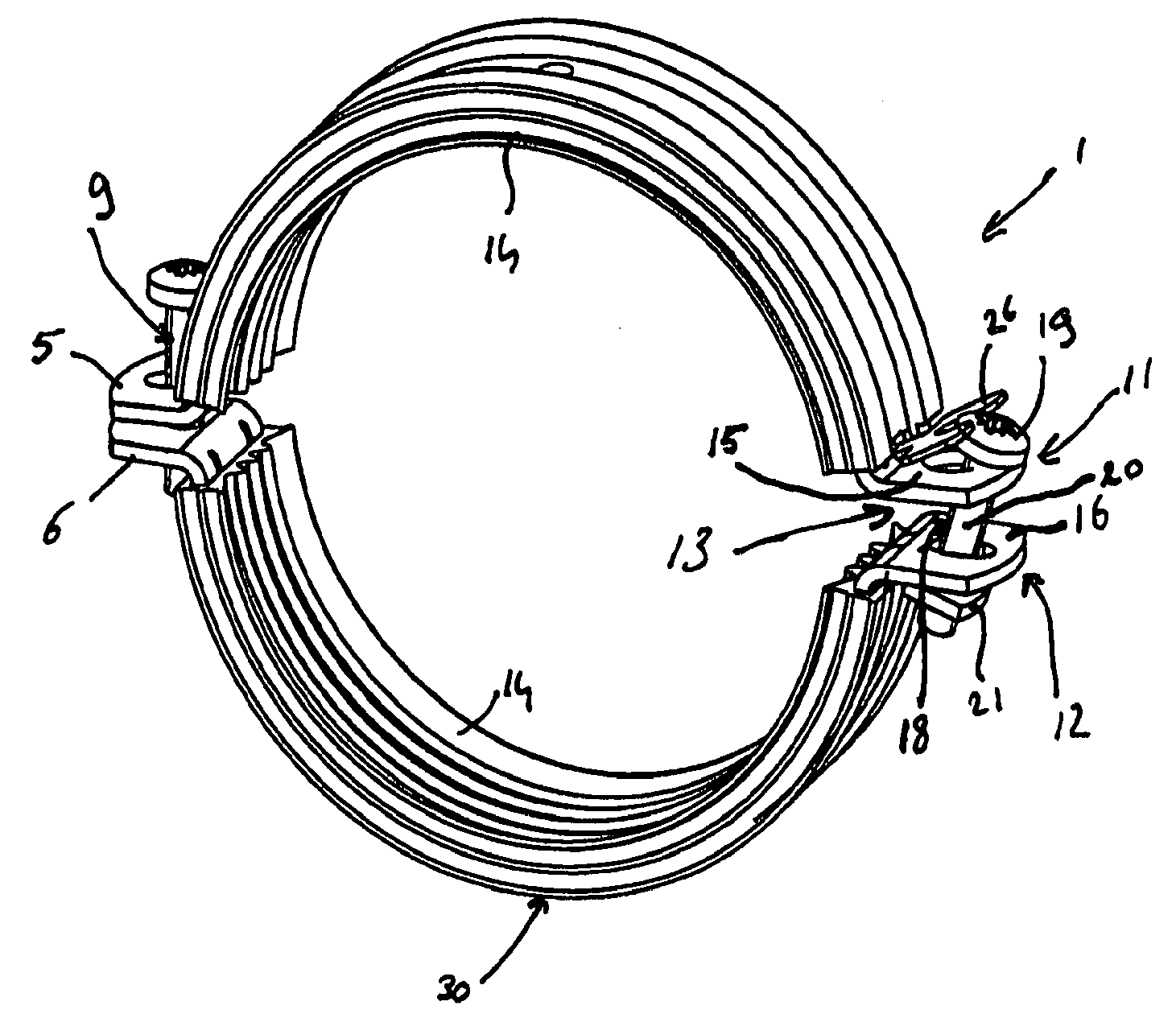
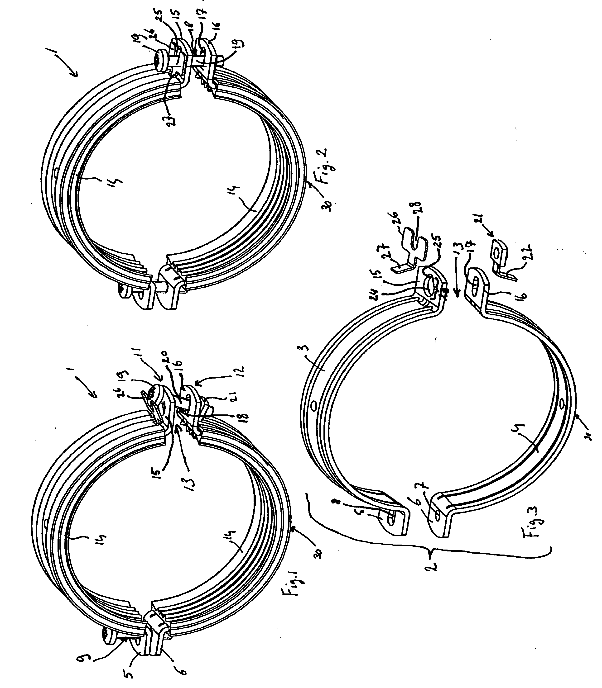
[0014]FIGS. 1-3 show a pipe clip 1 with a metal clip body 2 comprising two metal clip halves 3 and 4 respectively. The clip halves 3 and 4 are provided at one end with flanges 5 and 6 respectively. The flange 6 is provided with a hole 7 which is provided with a screw thread and into which a tightening screw 9 can be screwed. The flange 5 is provided with an elongate hole 8 through which the shank of the tightening screw 9 can be inserted. The elongate shape of the hole 8 allows the clip half 3 to be moved in a hinging manner in relation to the other clip half 4 around a hinge axis which is substantially parallel to the axial direction of the clip 1, when the tightening screw 9 has not been fully tightened. Per se, the hole 8 could also be shaped differently, provided that a hinging movement between the clip halves is possible. Per se, the clip halves 3, 4, could also be connected by means of other hinging means.

[0015]The clip body 2 has a first end 11 and a second end 12 which delim...


PUM


Abstract

The invention relates to a pipe clip for fastening a pipe to a wall, ceiling or another support. The pipe clip comprises a clip body with an opening for attaching the pipe clip around the pipe, which opening is delimited by a first and a second end of the clip body. The pipe clip further comprises a tightening element comprising a head and a shank, the head of which tightening element engages with the first end of the clip body, and also a female fastening element which is pivotably connected to the second end of the clip body and wherein the shank of the tightening element is inserted. The first end of the clip body comprises a first flange with a recess for the shank of the tightening element, which recess has dimensions such that the head of the tightening element fits therethrough. A arresting plate is pivotably attached to the side of the first flange that is facing away from the second end of the clip body. The arresting plate has a recess which is open on one side for the shank of the tightening element. The various aspects are formed in such a way that when the head of the tightening element is pressed through the recess in the first flange against the arresting plate during closing of the clip body, the arresting plate is pivoted in such a way that the shank of the tightening element is received in the recess of the arresting plate via the open end.

Description

BACKGROUND OF THE INVENTION[0001]The invention relates to a pipe clip for fastening a pipe to a wall, ceiling or another support. The pipe clip comprises a clip body with an opening for attaching the pipe clip around the pipe, which opening is delimited by a first and a second end of the clip body. The pipe clip furthermore comprises a tightening element comprising a head and a shank, the head of which tightening element engages with the first end of the clip body. The pipe clip also comprises a female fastening element which is pivotably connected to the second end of the clip body and wherein the shank of the tightening element is inserted.[0002]This type of pipe clip is known, for example from EP 1 431 641 A2 and DE 34 39 418. The known pipe clips have a clip body with an opening for attaching the pipe clip around the pipe, which opening is delimited by a first and a second end of the clip body. An integrally formed first and second flange are respectively located at the first en...

Claims


Application Information

Patent Timeline
Patent Type & Authority Applications(United States)
IPC IPC(8): A44B21/00A44B99/00
CPCY10T24/1441F16L3/1016
Inventor VAN WALRAVEN, JAN
Owner J VAN WALRAVEN
Why Eureka
Try Eureka