High power microjet cooler

a micro-jet cooler and high-power technology, applied in the field of high-power micro-jet coolers, can solve the problems of uneven cooling of the target, high heat/cooling transfer rate decrease, and undesirably increase the power flux, so as to enhance the thermal control of the assembly, and enhance the thermal control of the cooling plate

Inactive Publication Date: 2008-11-20
INT BUSINESS MASCH CORP
View PDF6 Cites 0 Cited by
  • Summary
  • Abstract
  • Description
  • Claims
  • Application Information

AI Technical Summary

Benefits of technology

[0009]It is another object of the present invention to provide thermal fluid assemblies, and methods of making such assemblies, that maximize heat transfer rates while enabling low pressure drops.
[0011]Still another object of the present invention is to provide thermal fluid assemblies, and methods of making such assemblies, that are consistent, reliable, time efficient and cost effective.
[0014]The above and other objects, which will be apparent to those skilled in art, are achieved in the present invention, which is directed to a distribution assembly for thermal control of a substrate. The assembly includes a plate having predetermined surface features residing on an exposed surface area thereof, and a manifold attached to the plate. The manifold has a microjet array and a distributed drain. A cavity resides between the manifold and the exposed surface area of the plate and the surface features. The microjet array emits a fluid, whereby the predetermined surface features delay a velocity decay of the fluid within the cavity, particularly within a wall jet region of the cavity, thereby enhancing thermal control of the assembly.
[0017]In another aspect, the invention is directed to a system for thermal heat transfer. The system includes a substrate having a temperature in need of modulating, and a cooling plate attached to the substrate. The cooling plate has an exposed surface area with predetermined surface features. A manifold is attached to the cooling plate, whereby the manifold has a microjet array and a distributed drain. A cavity resides between the manifold and the exposed surface area of the cooling plate, whereby the microjet array emits a fluid into the cavity for contact with such exposed surface area. The surface features delay a velocity decay of the fluid, thereby enhancing thermal control of the cooling plate. By enhancing thermal control of the cooling plate, the temperature of the substrate is also controlled.
[0018]In still another aspect, the invention is directed to a method for thermally controlling a temperature. A plate having predetermined surface features residing on an exposed surface area thereof is provided along with a manifold having a distributed drain and a plurality of microjets for emitting a fluid. The plate is attached to the manifold such that the surface features avoid alignment with the microjets, thereby not interfering with the impinging jet stream ejected from the micojets. Upon emitting the fluid from the microjets, the fluid contacts the plate in locations of the exposed surface area that are surrounded by the surface features. In so doing, the predetermined surface features maintain a velocity distribution of the fluid at these locations where the fluid contacts the exposed surface area to delay a velocity decay of the fluid for enhancing thermal control of the assembly. Any spent fluid is removed via the distributed drain.

Problems solved by technology

Under such processing conditions, conventional thermal technologies, such as heat spreaders, heat sinks, and associated thermal interfaces, will undesirably increase the power flux and generate high thermal gradients along the cooling axis.
However, this high heat / cooling transfer rate decreases rapidly in areas of the surface not residing directly below the surface area being impinged, which leads to uneven cooling of the target.
Also, the lateral drains remove spent fluid in a radial flow pattern away from a fluid jet with a maximum velocity at the periphery of the jet array, and as such, are insufficient for cooling high power flux situations.
Current fluid jet arrays also require a high fluid flow rate, which in turn, results in an undesirable increase in pressure drop on the cooler.
Since increasing the fluid velocity typically increases cooling capabilities, an increase in fluid velocity in conventional cooling devices to provide high cooling capabilities, such as above 400 W / cm2, would deleteriously generate high operating pressures that exceed the device pressure limits.
As such, the pressure drop required to operate modern electronic devices having high power flux situations limits the extendibility of conventional cooling devices.

Method used


Image

  • High power microjet cooler
  • High power microjet cooler
  • High power microjet cooler

Examples


example

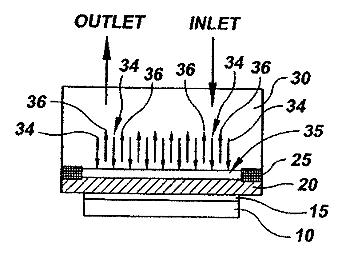
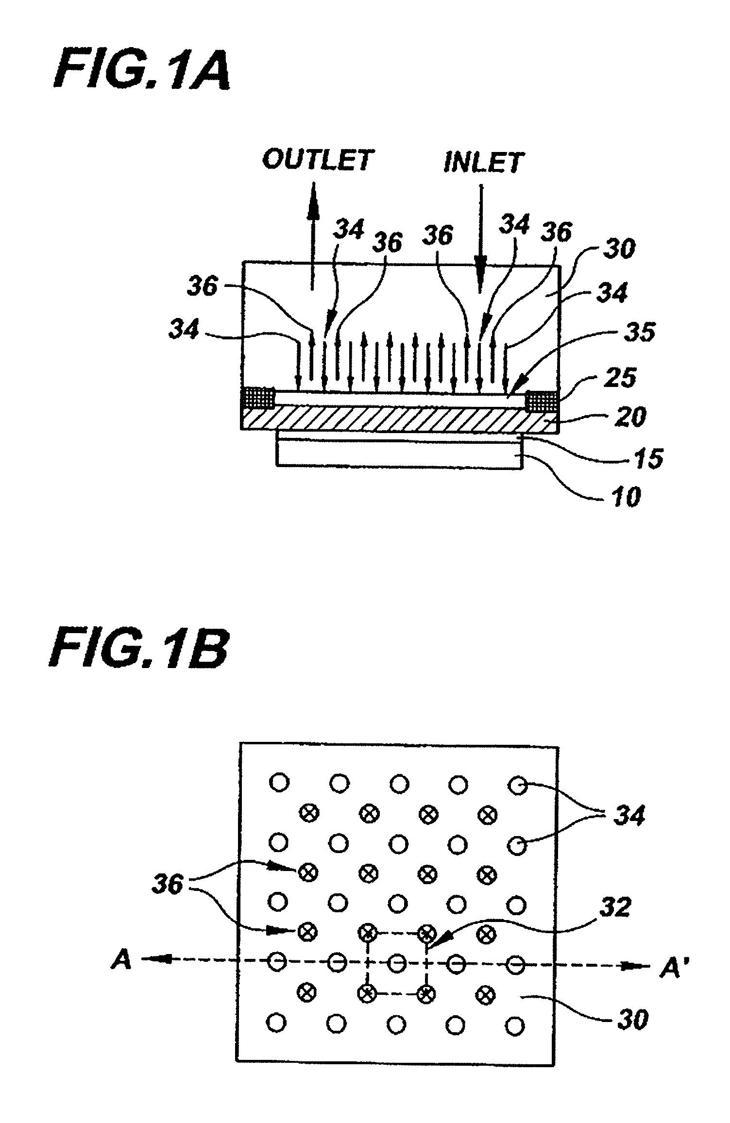
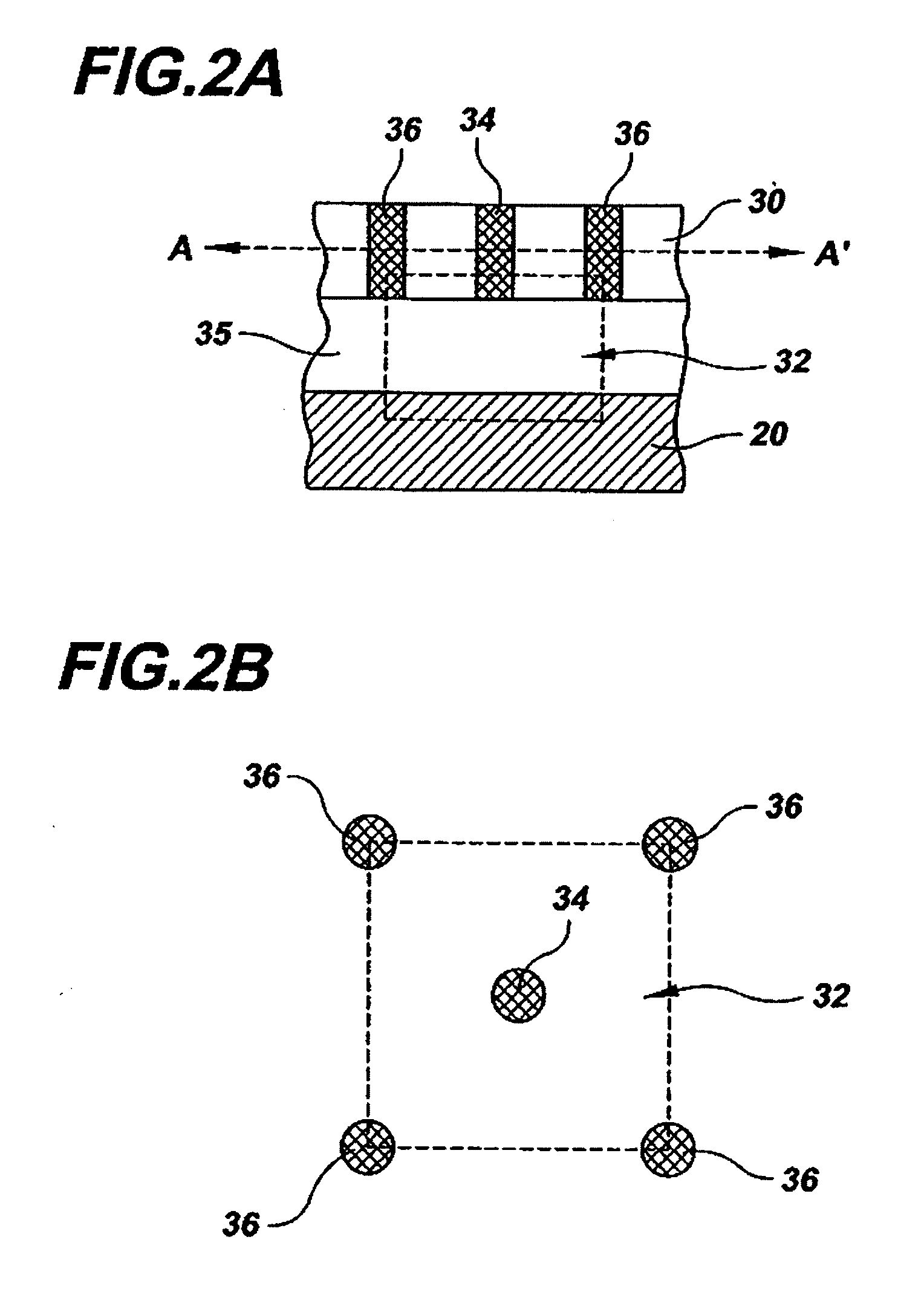
[0055]To test the distribution systems of the invention, a number of thermal assemblies having modified cooling plates with surface features were tested and compared against assemblies having cooling plates with planar surface areas. All tested assemblies included a 200 μm thick Si base having cooling cell dimensions of 250 μm by 250 μm with inlet / outlet diameters of about 70 μm. Water was used as the cooling fluid with a microjet velocity of 3 m / s and an inlet temperature of about 20° C. The flux at the base bottom was about 1000 W / cm2 while the gap between the cooling plate and the inlet / outlet array of the manifold was about 150 μm. The reference cooling capability (“q-ref”) is estimated using calculated convective coefficient over a 0.4 mm total silicon thickness (chip+base) with 45° C. total thermal budget and 50 μm TIM with k=3 W / mK.

[0056]The thermal performances of these assemblies is shown below whereby the cell types include a reference cell (“Ref-2”) having a planar coolin...


PUM


Abstract

A distribution apparatus, system and method for thermal control whereby a plate of a manifold assembly has predetermined surface features positioned on specific locations on a surface thereof for enhancing the cooling capabilities of the assembly. The predetermined surface features of the plate delay a velocity decay of a fluid impinging the surface of the plate, while also increase the surface area of the plate exposed to the impinging liquid, which in turn, maximize both the reliability and thermal performance of the overall thermal system at a given maximum operating pressure.

Description

BACKGROUND OF THE INVENTION[0001]1. Field of the Invention[0002]The present invention relates to cooling electronic devices, and in particular, to a cooling structure that enhances the cooling capability of high power dissipating devices and methods of manufacturing such cooling structure.[0003]2. Description of Related Art[0004]Modern electronic devices, such as those having increased power densities, operating frequencies and current leakages, as well as devices having small cooling fluid thermal budgets or having very high average power flux, are continually requiring improved thermal structures for providing enhanced thermal capabilities. For instance, in an electronic device having a high average power flux, a high power hot spot may dissipate 200 to 500 W / cm2, while a very high power hot spot may dissipate more than 500 W / cm2. Under such processing conditions, conventional thermal technologies, such as heat spreaders, heat sinks, and associated thermal interfaces, will undesir...

Claims


Application Information

Patent Timeline
Patent Type & Authority Applications(United States)
IPC IPC(8): F28D5/00F25D23/12
CPCF28F3/12F28F13/02H01L23/4735H01L2924/09701H01L2924/0002H01L2924/00
Inventor BEZAMA, RASCHID J.NATARAJAN, GOVINDARAJAN
Owner INT BUSINESS MASCH CORP
Why Eureka
Try Eureka