Hybrid inflator with temporary gas generator throttle

a technology of gas generator and hybrid inflator, which is applied in the direction of liquid handling, pedestrian/occupant safety arrangement, instruments, etc., can solve the problems of sagging evacuation, melting or scorching of fabric, and passengers being removed, so as to maximize the heat transfer rate

Active Publication Date: 2010-05-25
THE BF GOODRICH CO
View PDF8 Cites 2 Cited by
  • Summary
  • Abstract
  • Description
  • Claims
  • Application Information

AI Technical Summary

Benefits of technology

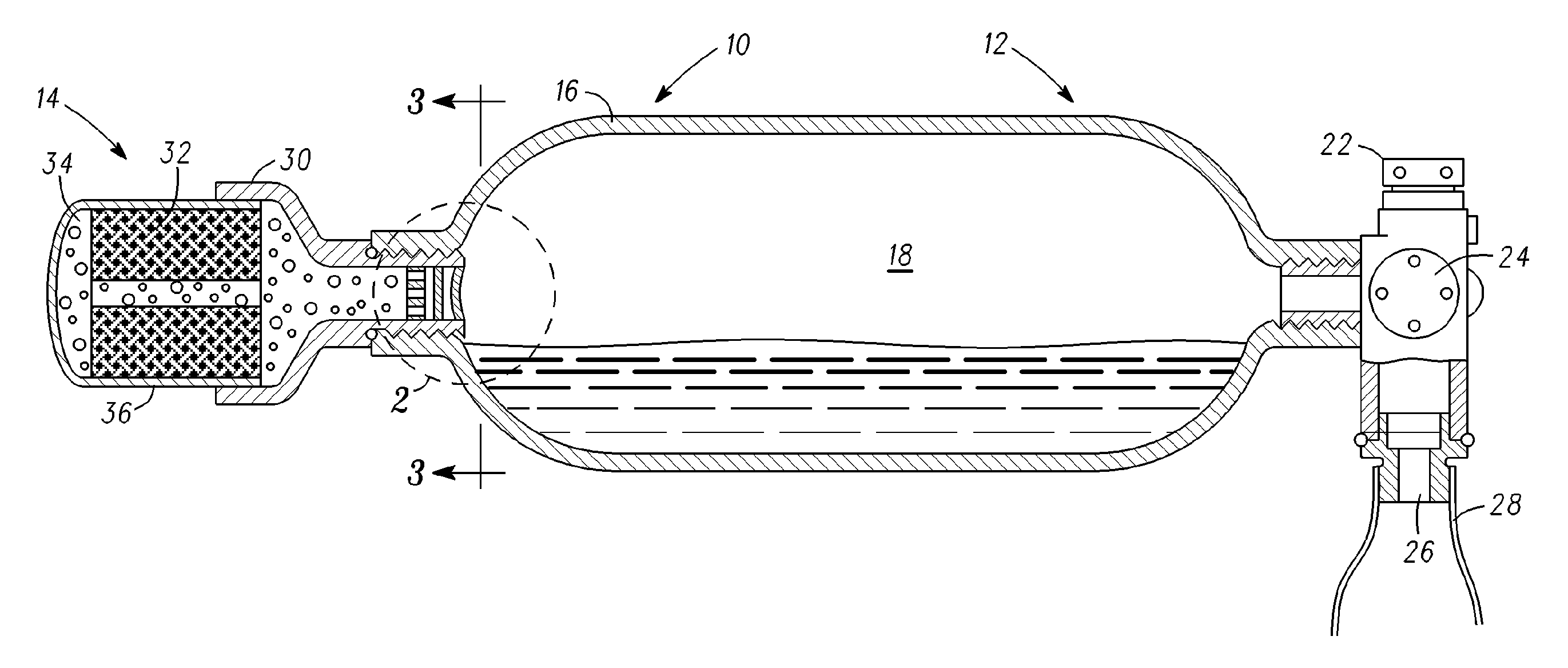
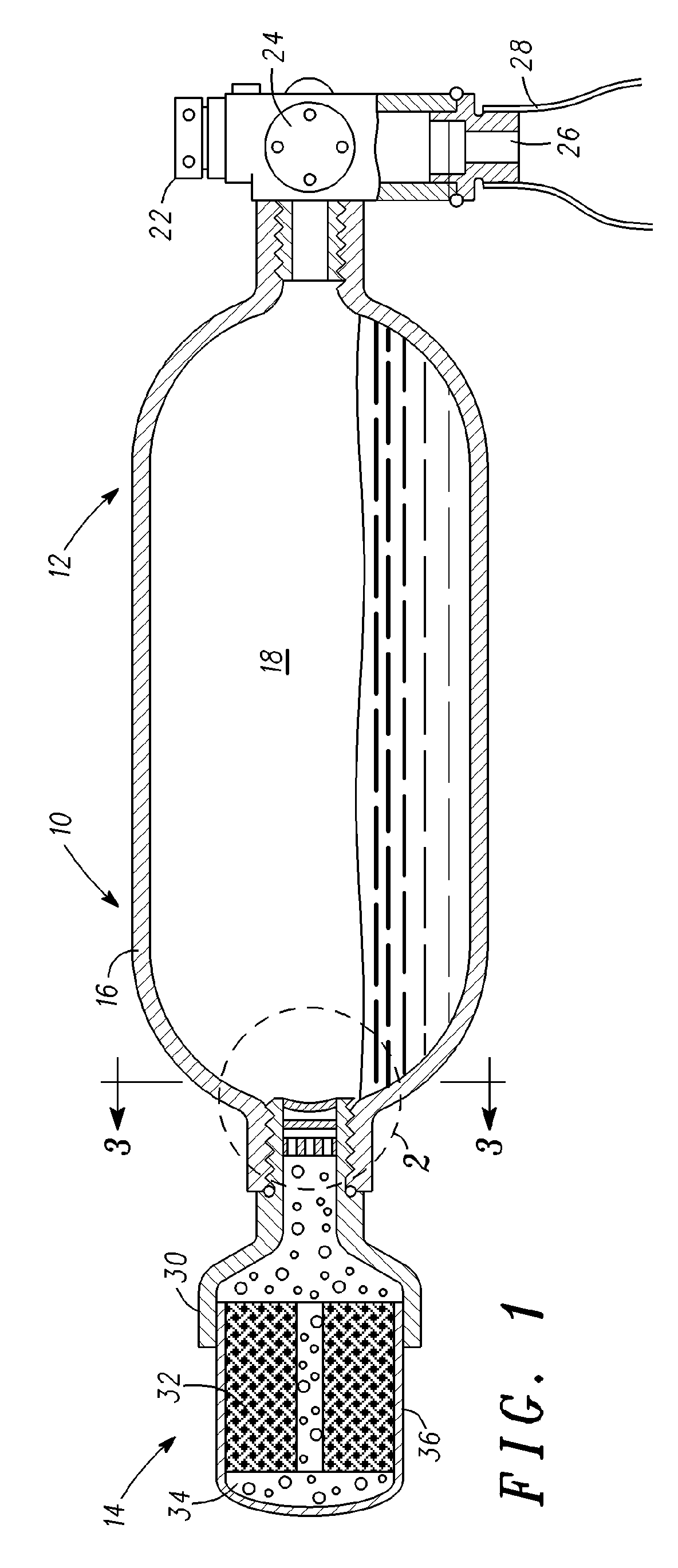
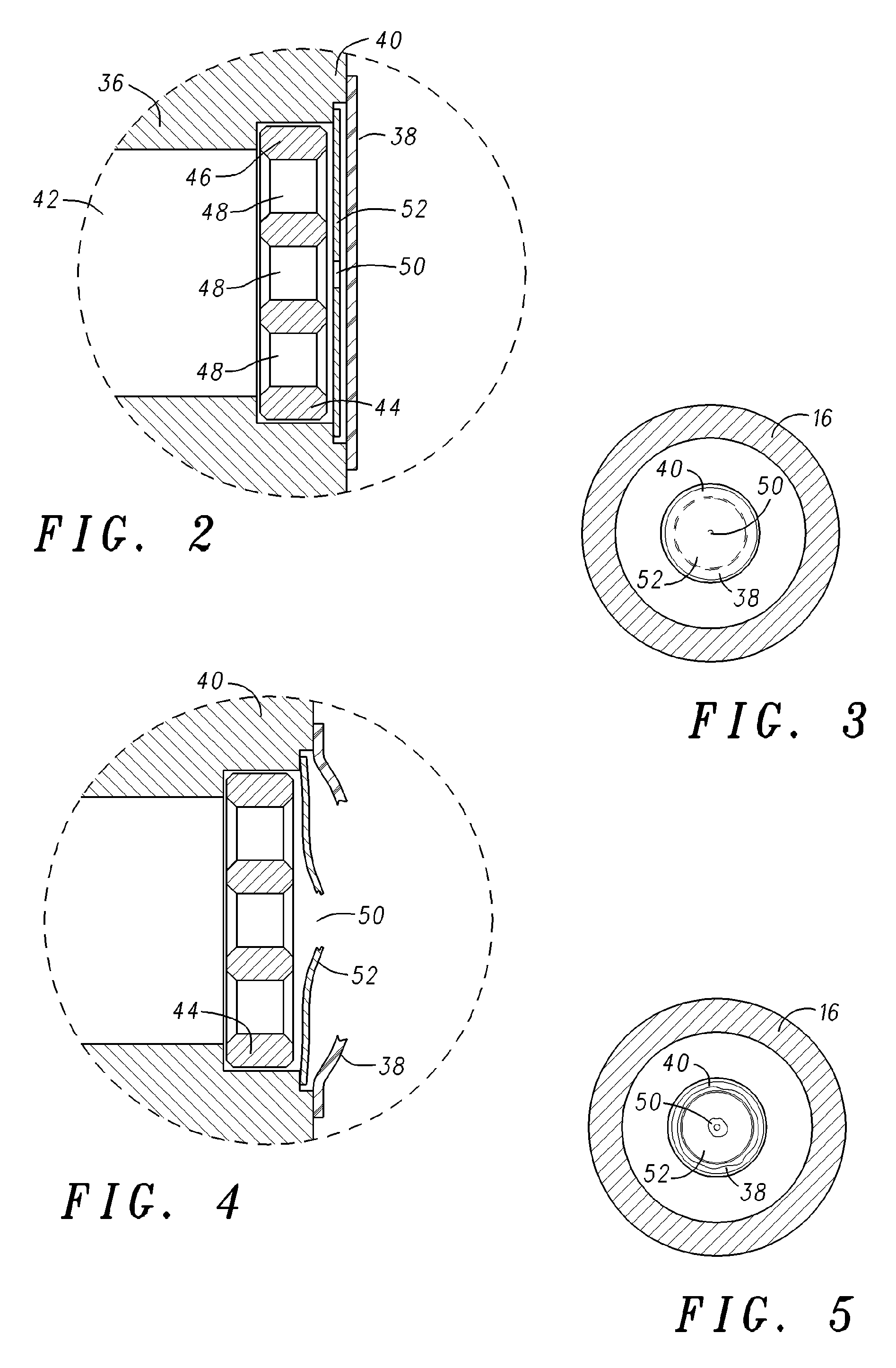
[0007]The present invention comprises a dual stage hybrid inflation device including a first stage gas source comprising a liquefied gas stored in a first stage pressure vessel and a second stage gas source comprising a gas generator having a gas output directed into the first stage pressure vessel. According to an embodiment of the present invention, the gas generator is isolated from the first stage pressure vessel by a frangible diaphragm that ruptures when the pressure in the gas generator exceeds the pressure in the first stage pressure vessel by a predetermined amount. The gas generator is also isolated from the first stage pressure vessel by an eroding nozzle that temporarily restricts the flow of gas from the gas generator to the first stage pressure vessel after the frangible diaphragm ruptures. The eroding nozzle initially restricts the flow of gas from the gas generator to the first stage pressure vessel to prevent a sudden pressure drop in the gas generator that would cause the pyrotechnic gas generating material to self extinguish. The nozzle then erodes away to allow an unobstructed flow of combustion products from the gas generator to the first stage pressure vessel, thereby maximizing the rate of heat transfer from the gas generator to the first stage pressure vessel. Because the pressure inside the gas generator is initially regulated by the flow restriction provided by the eroding nozzle, a higher percentage of liquefied carbon dioxide can be used as the stored inflation gas despite the very low vapor pressure of carbon dioxide at low temperatures.

Problems solved by technology

Emergencies at take-off and landing often demand swift removal of passengers from the aircraft because of the potential for injuries from fire, explosion, or sinking in water.
Pyrotechnic gas generators have an advantage in that they are small, lightweight, and produce a high volume of gas, however, the high temperature gas produced by a gas generator alone can cause numerous problems including sagging of the evacuation slide as the inflation gas cools and, in some cases melting or scorching of the fabric out of which the inflation slide is fabricated.
Use of stored compressed gas by itself, although simple, implicates a weight penalty that must be paid for carrying a pressure vessel having sufficient capacity (in terms of volume and pressure) to inflate the evacuation slide over the wide operational temperature range specified for such slides.
Additionally, where only a compressed gas is used to inflate the evacuation slide, a large drop in temperature occurs as the gases expand, often causing ice to form, which can block the flow of gas.
These problems are further exacerbated by the extreme temperature range over which these inflation systems are required to operate, typically from −65° F. to +165° F.
Unfortunately, at very low temperatures, the vapor pressure of Carbon Dioxide is too low (less than 200 psia at −65° F.) to enable combustion of the pyrotechnic materials used in modern hybrid inflators.

Method used


Image

  • Hybrid inflator with temporary gas generator throttle
  • Hybrid inflator with temporary gas generator throttle
  • Hybrid inflator with temporary gas generator throttle

Examples


Embodiment Construction

[0016]The drawing figures are intended to illustrate to the general manner of construction and are not necessarily to scale. In the detailed description and in the drawing figures, specific illustrative examples are shown and herein described in detail. It should be understood, however, that the drawing figures and detailed description are not intended to limit the invention to the particular form disclosed, but are merely illustrative and intended to teach one of ordinary skill how to make and / or use the invention claimed herein and for setting forth the best mode for carrying out the invention.

[0017]The present invention is directed to a method and apparatus for inflating an inflatable device such as an aircraft emergency evacuation slide over a wide range of operating temperatures, typically −65° F. to +165° F. With reference to the drawing figures, a cross-sectional view of an inflator incorporating features of the present invention is shown in FIG. 1. Inflator 10 comprises a fi...


PUM


Abstract

A dual stage hybrid inflation device includes a first stage gas source including a liquefied gas stored in a first stage pressure vessel and a second stage gas source including a gas generator having a gas output directed into the first stage pressure vessel. The gas generator is isolated from the first stage pressure vessel by a frangible diaphragm that ruptures when the pressure in the gas generator exceeds the pressure in the first stage pressure vessel by a predetermined amount. The gas generator is also isolated from the first stage pressure vessel by an eroding nozzle that temporarily restricts the flow of gas from the gas generator to the first stage pressure vessel after the frangible diaphragm ruptures. The eroding nozzle initially restricts the flow of gas from the gas generator to the first stage pressure vessel to prevent a sudden pressure drop in the gas generator that would cause the pyrotechnic gas generating material to self extinguish. The nozzle then erodes away to allow an unrestricted flow of combustion products from the gas generator to the first stage pressure vessel.

Description

BACKGROUND OF THE INVENTION[0001]This invention relates to emergency evacuation equipment for aircraft, in particular to an inflation device for inflating an inflatable aircraft evacuation slide or other inflatable device.[0002]The requirement for reliably evacuating airline passengers in the event of an emergency is well known. Emergencies at take-off and landing often demand swift removal of passengers from the aircraft because of the potential for injuries from fire, explosion, or sinking in water. A conventional method of quickly evacuating a large number of passengers from an aircraft is to provide multiple emergency exits, each of which is equipped with an inflatable evacuation slide.[0003]Current state of the art emergency evacuation slide systems comprise an inflatable evacuation slide that is stored in a folded, uninflated state together with a source of inflation gas. The source of inflation gas typically comprises a gas generator, stored compressed gas, or a combination t...

Claims


Application Information

Patent Timeline
Patent Type & Authority Patents(United States)
IPC IPC(8): B67D7/00
CPCB60R21/272B60R2021/0093Y10T137/1714Y10T137/1647B60R2021/26094
Inventor BOCK, CHRISTOPHER J.WIEBERS, GREGORY L.
Owner THE BF GOODRICH CO
Why Eureka
Try Eureka