Welding torch cable strain relief system and method

a strain relief system and welding torch technology, applied in the direction of welding coupling means, welding apparatus, manufacturing tools, etc., can solve the problems of conduit damage, conduit kink, conduit droop, etc., to avoid or reduce the strain in the supply conduit of welding torch.

Inactive Publication Date: 2008-11-20
ILLINOIS TOOL WORKS INC
View PDF5 Cites 5 Cited by
  • Summary
  • Abstract
  • Description
  • Claims
  • Application Information

AI Technical Summary

Benefits of technology

[0007]The present invention provides a novel technique for avoiding or reducing strain in welding torch supply conduits designed to respond to such needs. The technique makes use of a stiffener that is disposed adjacent to conduits exiting a welding torch. The stiffener may be housed in a jacket that may be wrapped around the conduits. The jacket may be held closely adjacent to the welding torch by various mechanisms, such that the stiffener remains in place. The stiffener may also be incorporated, such as by molding, into an extension of the welding torch handle.

Problems solved by technology

A persistent problem in such welding applications is the weight of these supply conduits, and the consequent tendency of the conduits to droop as they exit the welding torch.
However, these do not provide sufficient rigidity to avoid straining the conduits over extended periods of use and large numbers of cycles of flexure.
Ultimately, the conduits may become damaged or even kink due to an excessively steep angle or radius of curvature at the point where they exit the torch and lead back to the welding supply sources.
While certain arrangements may reduce this angle or radius, these also present other drawbacks.
While this does effectively reduce the angle at which the conduits exit the welding torch, such arrangements make it extremely difficult to service the conduits.

Method used


Image

  • Welding torch cable strain relief system and method
  • Welding torch cable strain relief system and method
  • Welding torch cable strain relief system and method

Examples


Embodiment Construction

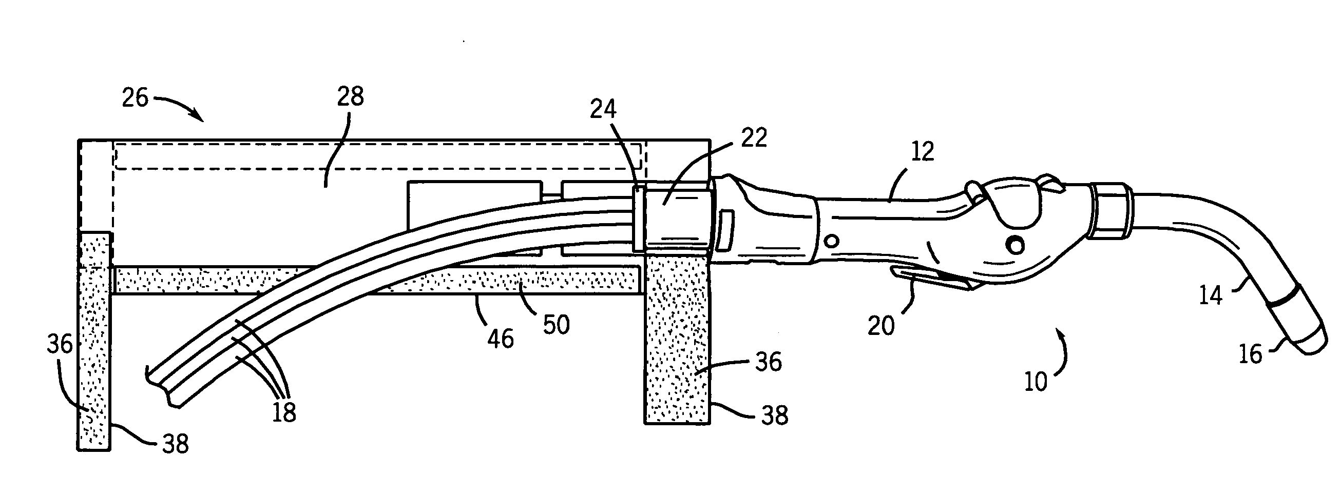
[0019]Turning now to the drawings, and referring first to FIG. 1, a welding torch is illustrated and designated generally by reference numeral 10. As will be appreciated by those skilled in the art, the torch, when placed in service, will be coupled to a source of welding power, as well as to other resources, such as a source of continuous wire electrode. The wire electrode and power source are typically provided in a welding base unit (not shown) which may be designed for drawing electrical power from the power grid or from a mobile power sources, such as an engine-driven generator (not shown). The welding resources, in the illustrated embodiment, may also typically include a source of inert gas which can be used to surround the electrode and weld during the welding operation. The illustrated welding torch is designed for MIG welding, such as with different sizes and grades of aluminum electrode wire.

[0020]The welding torch 10 shown in FIG. 1 has a body or handle 12 that terminates...


PUM

PropertyMeasurementUnit
widthaaaaaaaaaa
lengthaaaaaaaaaa
curvatureaaaaaaaaaa

Abstract

Conduits exiting from a welding torch handle are supported by a stiffening arrangement to limit the angle or radius of curvature of the conduits and thereby to limit strain and possible damage. The stiffening arrangement may include a stiffener that does not extend completely around the conduits, but is captured in a jacket that may be secured to the torch handle and wrapped around the conduits. Alternatively, an integral stiffener or stiffener assembly may include a tongue-like-stiffener extending from the handle to support the conduits and to limit their radius of curvature as they exit the handle.

Description

BACKGROUND[0001]The present invention relates generally to the field of welding systems and welding apparatus. More particularly, the invention relates to a technique for avoiding damage to welding supply conduits coupled to welding torches.[0002]A wide range of applications are known for various welding systems. In general, arc welding systems produce a weld by passing an AC or DC current through an electrode and a workpiece. The voltage applied between these components forms an arc which heats the electrode and the workpiece. In certain applications, such as metal inert gas (MIG) welding, a continuous feed of wire electrode is directed to the location where the arc is established. The wire is melted, along with materials in the neighborhood of the desired weld, to produce a weld bead. The arc and bead may be protected by gasses, fluxes, and so forth, depending upon the particular welding technique employed.[0003]In welding systems, such as the MIG systems discussed above, various ...

Claims


Application Information

Patent Timeline
Patent Type & Authority Applications(United States)
IPC IPC(8): B23K9/32
CPCB23K9/32B23K9/323
Inventor CHRISTOPHER, MARK RICHARDPULS, KENNETH J.
Owner ILLINOIS TOOL WORKS INC
Why Eureka
Try Eureka