
Stand for a drying gun supporting frame

a technology for drying guns and supporting frames, which is applied in the direction of machine supports, valve housings, lighting and heating apparatus, etc., can solve the problems of hard sealing with nuts, and achieve the effect of providing stability and low altitud

Inactive Publication Date: 2008-11-20
JOU WUU CHEAU
View PDF3 Cites 1 Cited by
  • Summary
  • Abstract
  • Description
  • Claims
  • Application Information

AI Technical Summary

Benefits of technology

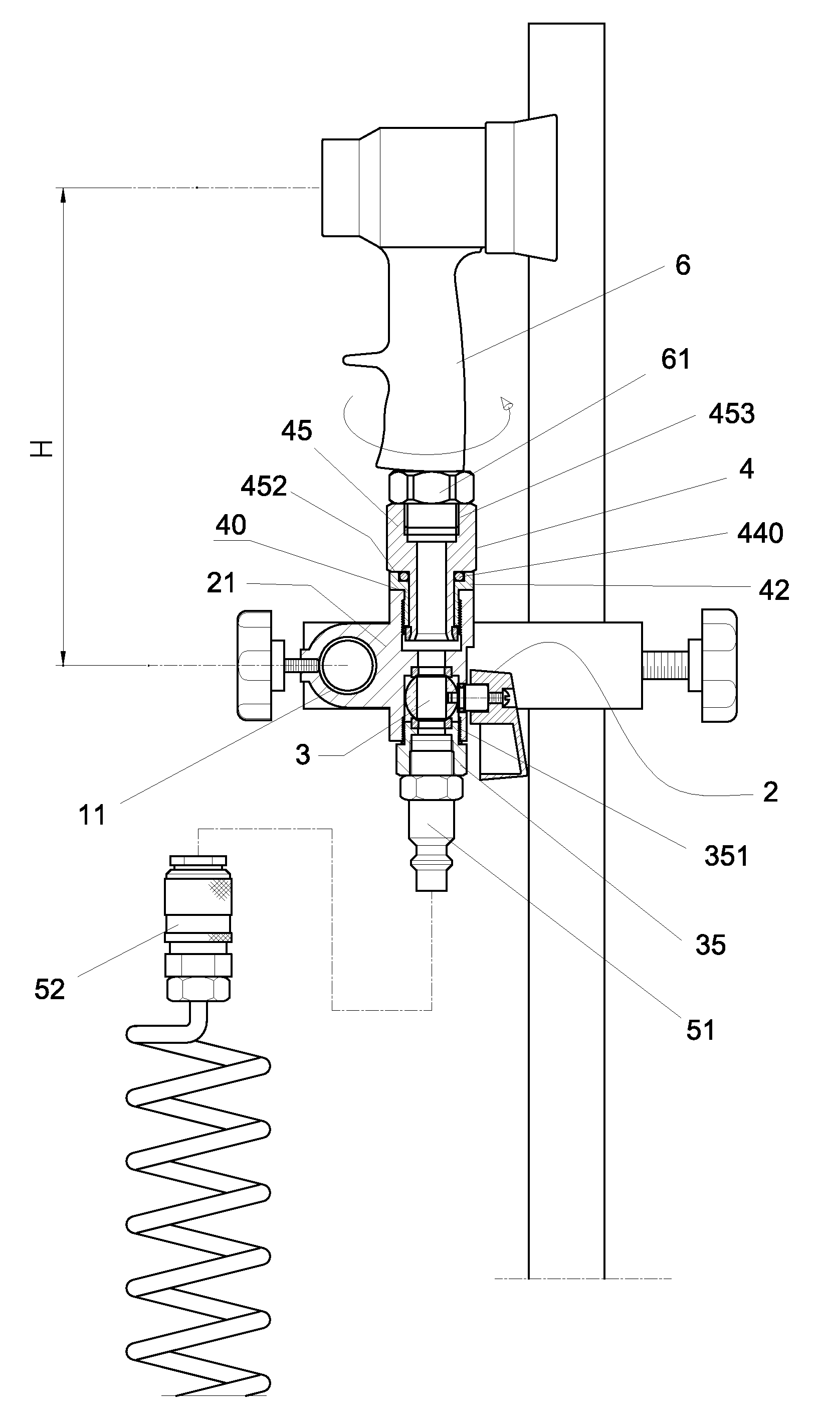
[0007]It is the main object of the present invention to provide a stand for a drying gun supporting frame, which is designed to have a lower altitude between the balancing pipe and the drying gun outlet so as to provide a stability of the drying gun.

Problems solved by technology

When turning the drying gun 15, it requires excessive torque, causing the drying gun 15 in an unstable condition so that it is hard to secure with a nut 18.

Method used


Image

  • Stand for a drying gun supporting frame
  • Stand for a drying gun supporting frame
  • Stand for a drying gun supporting frame

Examples


Embodiment Construction

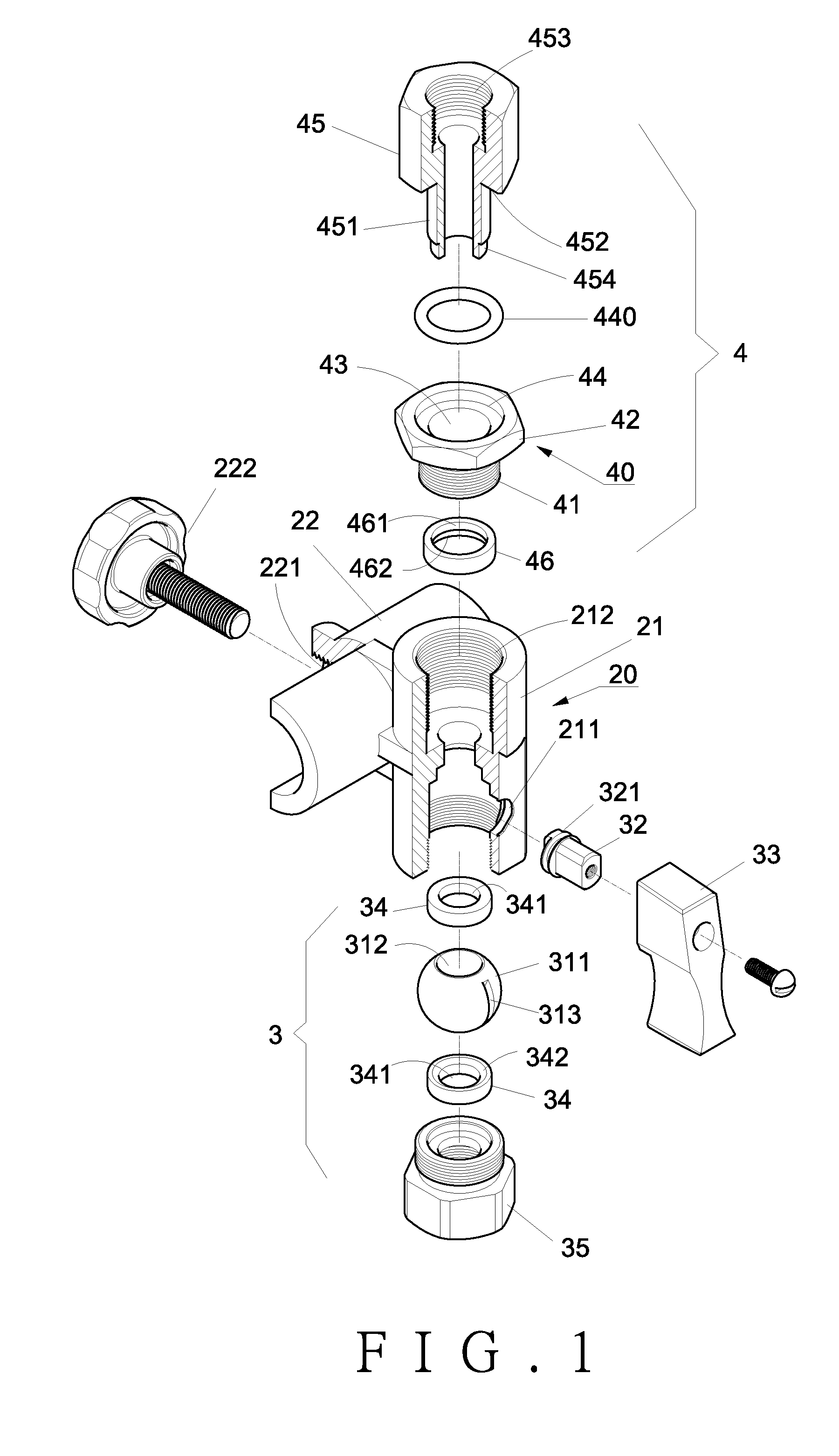
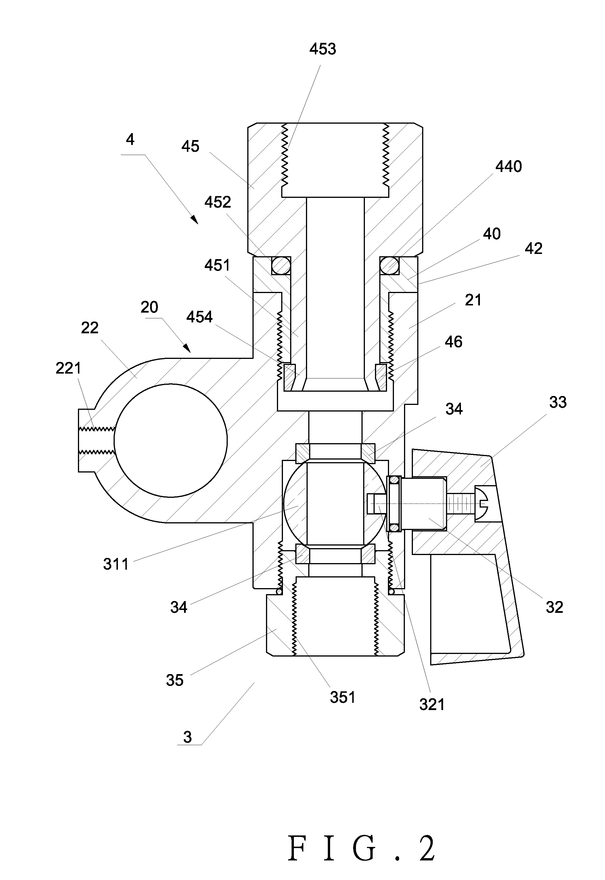
[0016]As shown in FIGS. 1 and 2, the present invention comprises a stand 20 having a body 21 and a socket 22 at 90 degrees to the body 21.

[0017]The body 21 is a hollow tube adapted to receive a spherical valve 3 therein. A connecting unit 4 is pivotally connected to the top of the body 21.

[0018]The socket 22 is a hollow tube having a threaded hole 221 at one side for a manual screw 222 to be threaded therein.

[0019]The spherical valve 3 accommodated in the body 21 comprises a ball 311 having a through hole 312 therein. The ball 311 has two flat ends. One side of the ball 311 is formed with a slot 313 for engagement of a tenon 32 provided at one end of a linking rod 32. The other end of the linking rod 32 protrudes outwardly from an aperture 211 of the body 21 and is secured with a knob 33. Two washers 34 are disposed at the two flat ends of the ball 311. Each washer 34 has a central hole 341 and a cone edge 342 which is in touch with the ball 311. A cap 35 is threaded to the bottom o...


PUM


Abstract

A stand for a drying gun supporting frame includes a body and a socket at 90 degrees to the body. A spherical valve is disposed in the body, and a connecting unit is provided at the top of the body. The socket has a threaded hole at one side to receive a manual screw therein so as to secure a balancing pipe thereat. The spherical valve disposed in the body comprises a ball, washers, a cap and a linking rod. The altitude of the spherical valve is lower than the center of the balancing pipe, which lowers the outlet of the drying gun and provides a steady operation of the drying gun.

Description

BACKGROUND OF THE INVENTION[0001]1. Field of the Invention[0002]The present invention relates to a stand for a drying gun supporting frame, and more particularly to a stand for supporting a drying gun at a lower position to provide a steady operation status.[0003]2. Description of the Prior Art[0004]As shown in FIG. 6, a conventional drying gun supporting frame 1 comprises a stand 12 on a balancing pipe 11. The stand 12 is slidable and rotatable with respect to the balancing pipe 11. An air pipe 13 is provided at one side of the stand 12 for supplying pressurized air. The top of the stand 12 is connected with a female quick connector 14 to secure a drying gun 15 thereon. The bottom of the drying gun 15 is provided with a spherical valve 16, as shown in FIG. 7. The bottom of the spherical valve 16 is connected with a male quick connector 17 which is to facilitate quick connection with the female quick connector 14.[0005]As shown in FIGS. 7 and 8, there are three members mounted betwe...

Claims


Application Information

Patent Timeline
Patent Type & Authority Applications(United States)
IPC IPC(8): F16M11/00
CPCF16K27/067F26B21/004
Inventor JOU, WUU-CHEAU
Owner JOU WUU CHEAU
Learn More