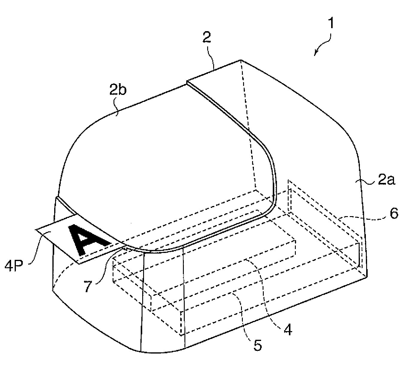
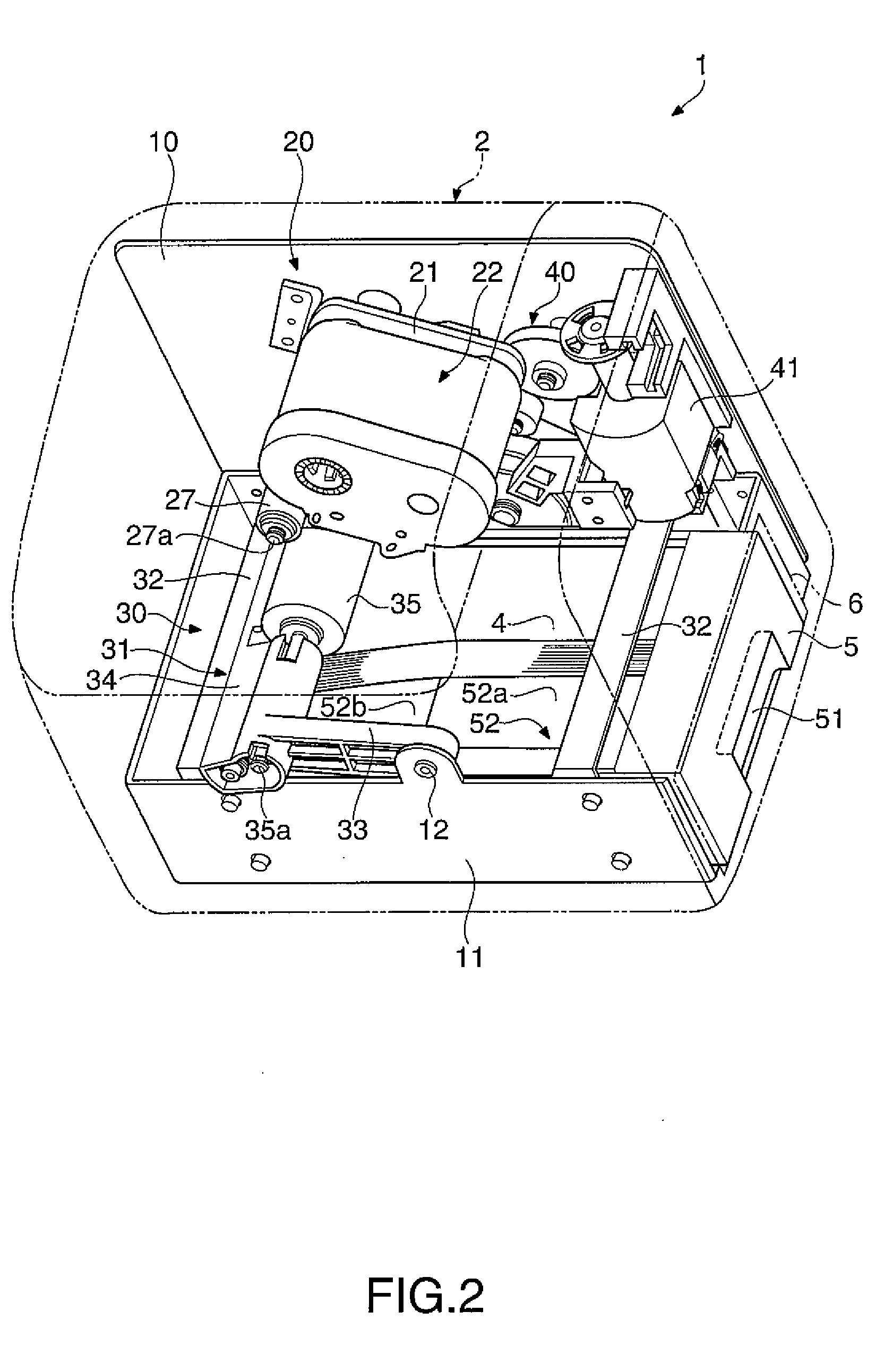
[0008]According to the paper feeder, only the uppermost sheet of paper is separated from the bundle of sheets of paper by deforming the sheet of paper at the uppermost of the bundle of sheets of paper with the roller. In this regard, the roller deforms the sheet of paper to separate it from the bundle of sheets of paper. Further, in the paper feeder, the tray for placement of the bundle of sheets of paper has the first placement surface and the second placement surface. The bundle of sheets of paper placed on the tray having such two placement surfaces is held in a shape along the first placement surface and the second placement surface, and the boundary position between the first placement surface and the second placement surface is an inflection point in the shape of the bundle of sheets of paper. The bundle of sheets of paper in this state is similar to the initial state in which the roller starts to deform the sheets of paper to separate the sheets of paper from the bundle of sheets of paper. When the roller starts to separate the uppermost sheet of paper, the uppermost sheet of paper starts to deform more easily and reliably for separating it from the bundle of sheets of paper than in the case where the bundle of sheets of paper are placed on a placement surface formed by one flat surface. Further, even the bundle of sheets of paper having a number of sheets of paper or the bundle of sheets of paper having higher stiffness can be smoothly deformed against the resistance of the bundle of sheets of paper. Furthermore, the bundle of sheets of paper is slid along the first placement surface and the second placement part with no convex obstacle or the like and smoothly placed on the tray. In this way, the paper feeder can smoothly insert the sheets of paper into the tray and reliably feed paper by separating the sheets of paper from the bundle of sheets of paper one by one.
[0010]According to the paper feeder, the bundle of sticky notes to be placed has the adhesive part and the free end part unconstrained by the adhesive, and only the uppermost sticky note is separated from the bundle of sticky notes by deforming the free end part of the sticky note at the uppermost of the bundle of sticky notes with the roller. In this regard, the roller deforms the sticky note to separate it from the bundle of sticky notes. Further, in the paper feeder, the tray for placement of the bundle of sticky notes has the first placement surface and the second placement surface. The bundle of sticky notes placed on the tray having such two placement surfaces is held in a shape along the first placement surface and the second placement surface, and the boundary position between the first placement surface and the second placement surface is an inflection point in the shape of the bundle of sheets of paper. The bundle of sticky notes in this state is similar to the initial state in which the roller starts to deform the sticky notes to separate the sticky notes from the bundle of sticky notes. When the roller starts to flip up the uppermost sticky note, the uppermost sticky note starts to deform more easily and reliably for separating from the bundle of sticky notes than in the case where the bundle of sticky notes is placed on a placement surface formed by one flat surface. Further, even the bundle of sticky notes having a number of sticky notes or the bundle of sticky notes having higher stiffness can be smoothly deformed against the resistance of the bundle of sticky notes. Furthermore, the bundle of sticky notes is slid along the first placement surface and the second placement part with no convex obstacle or the like and smoothly placed on the tray. In this way, the paper feeder can smoothly insert the sticky notes into the tray and reliably feed paper by separating the sticky notes from the bundle of sticky notes one by one.
[0012]According to the configuration, the second placement surface is a slope inclined relative to the first placement surface, and the bundle of sticky notes placed on the tray is bent to have a slope at the side of the roller along the first placement surface and the second placement surface. Therefore, even the bundle of sticky notes with few sticky notes left or the bundle of sticky notes having lower stiffness can be placed along the first placement surface and the second placement surface and constantly maintained in the fixed bent condition, and all of the sticky notes can be separated smoothly under the same condition from the bundle of sticky notes by the roller.
[0014]According to the configuration, the tray has the first placement surface and the second placement surface respectively forming the step-like shapes, and the first placement surface and the second placement surface formed by the steps can be machined more easily in manufacturing and finished more accurately than the slope. The bundle of sheets of paper placed on the tray is bent and placed with a gap between the placement surface at the lower step side and itself. Therefore, using the gap, the pressure by the roller or the control part can be adjusted for adjustment of the degree of bending, and proper bending can be secured with respect to the bundle of sticky notes with higher stiffness or the like by making the pressure higher. In this way, the paper feeder having the stepped first placement surface and second placement surface can operate to more easily bend the sticky notes for separation from the bundle of sticky notes according to the material, stiffness, or the like of the bundle of sticky notes.
[0016]According to the configuration, the bundle of sticky notes is constantly in the fixed bent shape by placing the free end part of the bundle of sticky notes at the side of the second placement surface as the slope or step-like surface. Thereby, the sticky notes are reliably flipped up and separated from the bundle of sticky notes by the roller. Further, since the second placement surface has no projection that inhibits
insertion of the bundle of sticky notes, the bundle of sticky notes can be easily inserted along the second placement surface.


