

Machine track system and machine track segment
a technology of machine track and machine track, applied in the field of machine track system, can solve the problems of track design unique challenges, bending and/or separation of parts, and disparate vertical positions of parts of the track
- Summary
- Abstract
- Description
- Claims
- Application Information
AI Technical Summary
Benefits of technology
Problems solved by technology
Method used
Image

Examples
Embodiment Construction
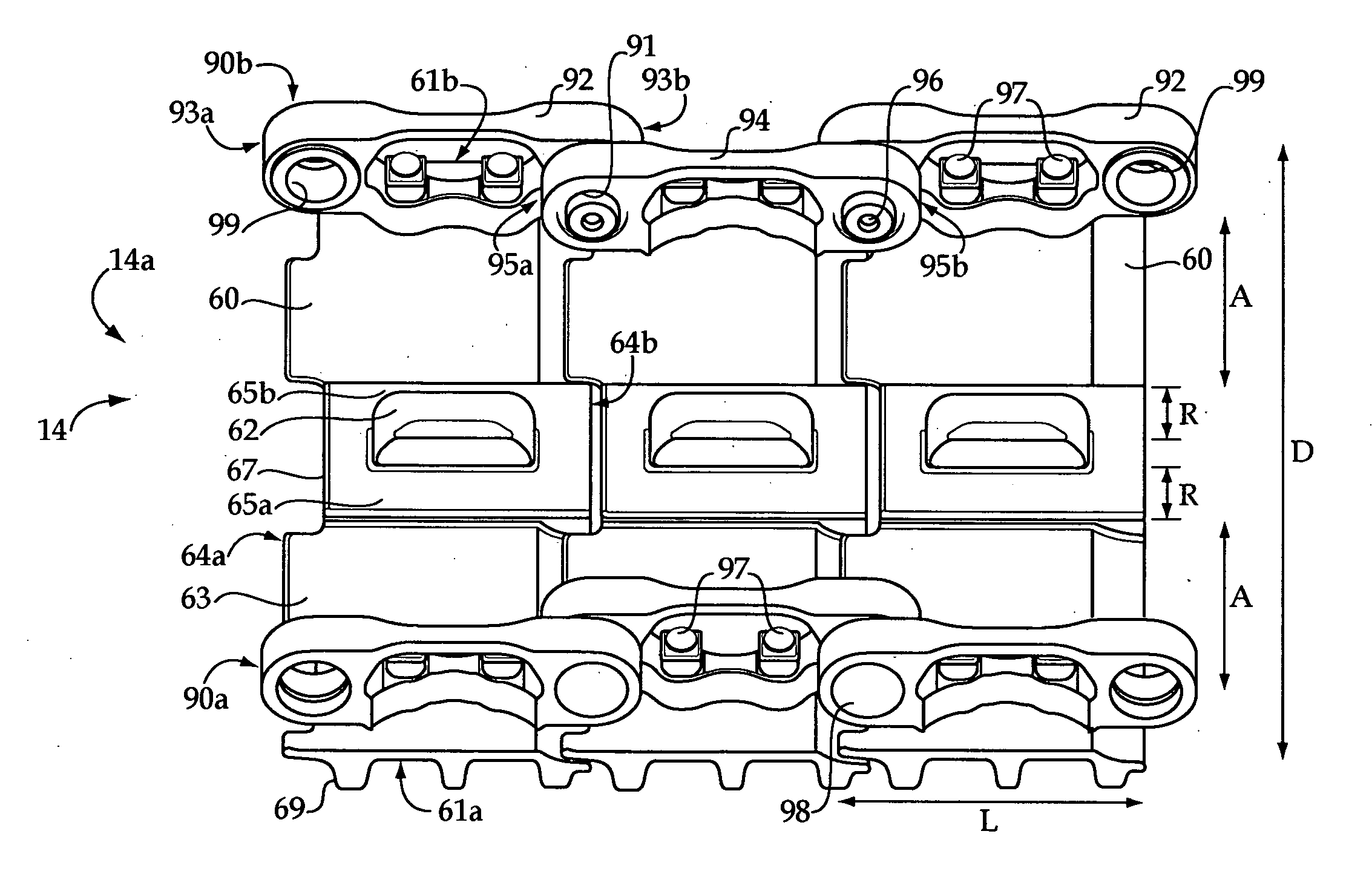
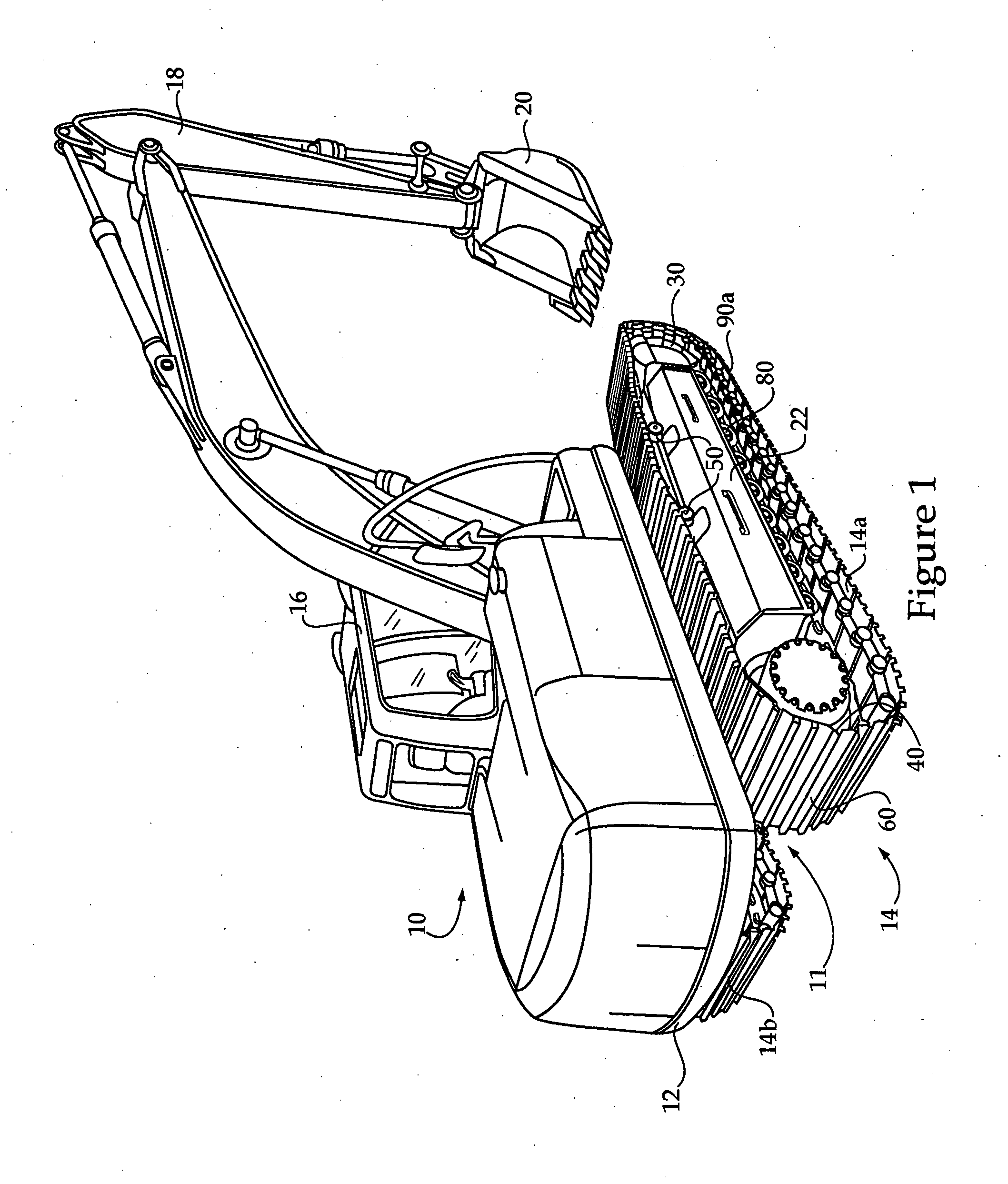
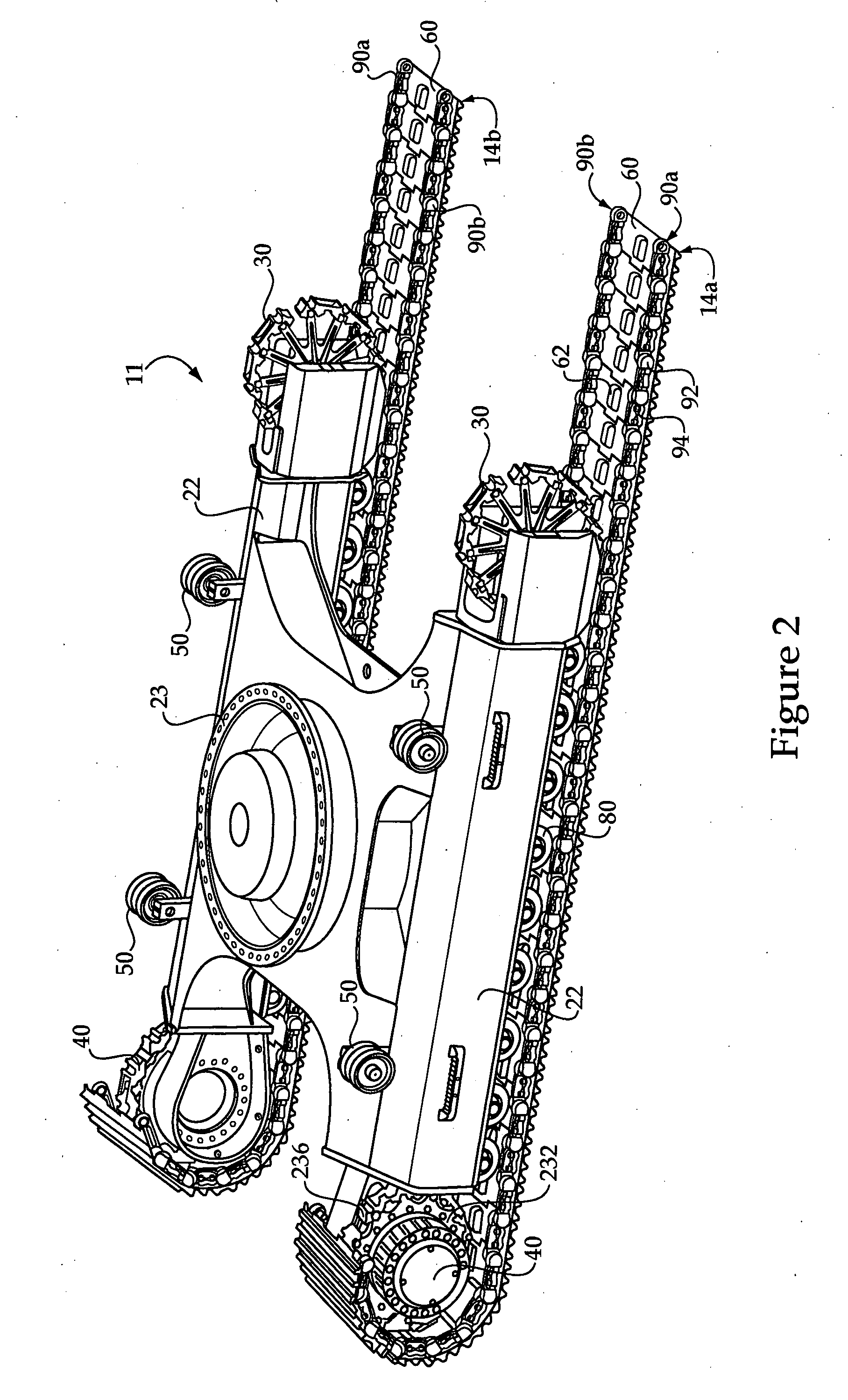
[0019]Referring to FIG. 1, there is shown a machine 10 having a frame 12 with a track system 14, including a first track 14a and a second track 14b positioned at opposite sides of frame 12. Machine 10 is shown in the context of an excavator having an operator cab 16, a linkage 18 and an implement 20 coupled with linkage 18. Tracks 14a and 14b are part of a machine undercarriage 11 coupled with frame 12 in a conventional manner. Each of tracks 14a and 14b include a plurality of coupled together track shoes 60 forming endless loops extending about a plurality of rotatable elements. In a typical design, an idler 30 and a drive sprocket 40 will be associated with each of tracks 14a and 14b and mounted to a track roller frame 22. A plurality of track rollers 80 may also be mounted to roller frame 22, and are associated with each of tracks 14a and 14b to support machine 10 and guide tracks 14a and 14b in desired paths, as further described herein. One or more carrier rollers 50 may also b...
PUM
| Property | Measurement | Unit |
|---|---|---|
| width | aaaaa | aaaaa |
| average distance | aaaaa | aaaaa |
| area | aaaaa | aaaaa |
Abstract
Description
Claims
Application Information