Wide Band Antenna Common to a Plurality of Frequencies

Inactive Publication Date: 2008-11-20
NAT INST OF INFORMATION & COMM TECH
View PDF5 Cites 15 Cited by
  • Summary
  • Abstract
  • Description
  • Claims
  • Application Information

AI Technical Summary

Benefits of technology

[0014]An object of the present invention is to provide an antenna common to a plurality of frequencies for c

Problems solved by technology

However, this may bring a disadvantage that the antenna structure becomes relatively complicated.
Further, since feeding

Method used


Image

  • Wide Band Antenna Common to a Plurality of Frequencies
  • Wide Band Antenna Common to a Plurality of Frequencies
  • Wide Band Antenna Common to a Plurality of Frequencies

Examples


Embodiment Construction

[0041]An embodiment of the present invention will be explained with reference to the drawings.

[0042]It is noted that various changes may be made in design of structure of the present invention without departing from the scope of the invention and conventional art such as the above documents may be applied to details in the structure of the present invention.

[0043]In general, since an antenna should be designed to include a band or resonance characteristics in accordance with the purpose of use to be the most preferred embodiment, it should be understood that the following embodiments are not universally the most preferred embodiment.

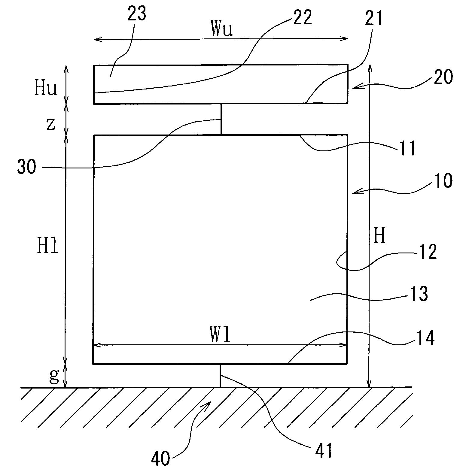
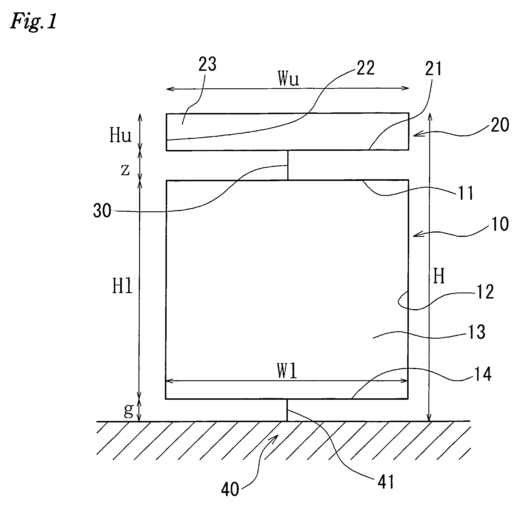
[0044]FIG. 1 is a front view of a wide band planar monopole antenna common to a plurality of frequencies according to the present invention.

[0045]Here, the wide band planar monopole antenna common to a plurality of frequencies provided on an infinite bottom plate is shown. In the example shown in FIG. 1, planar conductors are used as element part conduct...


PUM


Abstract

An antenna common to a plurality of frequencies in which a wide band of a UWB system can be covered while suppressing interference with other systems. The antenna comprises a plurality of element part conductors, coupling conductors for coupling them electrically, and a feeder for coupling one element part conductor electrically with a feeder part capable of feeding to that element part conductor, wherein respective element part conductors are concatenated sequentially by the coupling conductors. The element part conductor has a shape substantially symmetric to a line connecting the coupling conductors or the parts coupled with the feeder. Each coupling conductor is arranged substantially linearly and the plane part of each planar conductor is arranged substantially vertically.

Description

TECHNICAL FIELD[0001]The present invention relates to an antenna common to a plurality of frequencies, which shows a wide band characteristic, more particularly, a wide band antenna common to a plurality of frequencies, which shows a characteristic having a notch in a part of frequency band.BACKGROUND ART[0002]As basic antennas, a dipole antenna, a monopole antenna, an inverted L antenna, and a slit antenna are known.[0003]The dipole antenna is an antenna composed of two connected bars of conductor with quarter wavelength and is used as an antenna for FM broadcast or terrestrial television.[0004]The monopole antenna is considered as a detached half of the dipole antenna and is used as an antenna for AM broadcast, transceivers, or mobile telephones.[0005]The inverted L antenna is a modification of the monopole antenna and considered as an antenna having an antenna element bent at the base and widened. Since its shape may be small with respect to wavelength of radio wave and the anten...

Claims


Application Information

Patent Timeline
IPC IPC(8): H01Q9/30H01Q9/16H01Q1/38H01Q5/00H01Q5/10H01Q5/364H01Q9/36H01Q9/40
CPCH01Q9/285H01Q9/36H01Q9/40
Inventor RIKUTA, YUKOKOHNO, RYUJI
Owner NAT INST OF INFORMATION & COMM TECH
Why Eureka
Try Eureka