Image processing apparatus and method

a technology of image processing and image features, applied in the field of image processing apparatus and method, can solve the problems of unnatural, in-front/back relationship between real and virtual spaces, observer viewing the resulting image feels unnatural, etc., and achieve the effect of improving registration stability and preventing erroneous detection of image features

Inactive Publication Date: 2008-11-20
CANON KK
View PDF12 Cites 74 Cited by
  • Summary
  • Abstract
  • Description
  • Claims
  • Application Information

AI Technical Summary

Benefits of technology

[0033]The present invention provides a technique in which erroneous detection of image features can be prevented when an observation target object is occluded by an occluding object and registration stability can be improved.
[0034]The present invention further provides a technique using a measurement device arranged to measure the position and orientation of an occluding object, in which erroneous detection of image features can be prevented using information obtained from the measurement device when an observation target object is occluded by the occluding object and registration stability can be improved.

Problems solved by technology

One of the most serious problems with the AR technique is accurate registration between real and virtual spaces, and many attempts have been made to address this problem.
In a video see-through HMD, the problem of registration in AR involves accurate determination of the position and orientation of the image pickup apparatus in a scene (that is, in a reference coordinate system defined in the scene).
In an optical see-through HMD, the problem of registration involves accurate determination of the position and orientation of the HMD in a scene.
Another serious problem in AR technology, other than registration, is an occlusion problem in which determination of the in-front / behind relationship between real and virtual spaces is required.
If the occlusion effect is not taken into account, the virtual object is always rendered in front of the real object, and an observer viewing the resulting image feels unnatural.
In the above step (2), erroneous detection may occur if the accuracy of the rough position and rough orientation of the image pickup apparatus is low.
If such erroneous detection occurs, the iterative calculations may not be converged in the step (3), or the accuracy of the obtained position and orientation of the image pickup apparatus may be low, resulting in low-accuracy AR registration.
The point-feature-based methods also have a problem of erroneous detection, like the edge-based methods.
Therefore, it is difficult to extract the background by performing simple processing such as chroma-keying, and it is also difficult to adopt the technique proposed by Orad Hi-Tec systems Ltd. to avoid erroneous detection of natural features on the background image.
In the related art, however, information concerning the in-front / behind relationship is not used for natural feature detection.
In the related art, however, information concerning the measured position and orientation of the occluding object is not used for natural feature detection.

Method used


Image

  • Image processing apparatus and method
  • Image processing apparatus and method
  • Image processing apparatus and method

Examples


first embodiment

[0057]A first embodiment of the present invention will be described with respect to a registration method using edges detected on an image. More specifically, a position and orientation measurement apparatus and a position and orientation measurement method for determining the position and orientation of an observer relative to an observation target object observed by the observer when the observation target is occluded by a hand of the observer will be described.

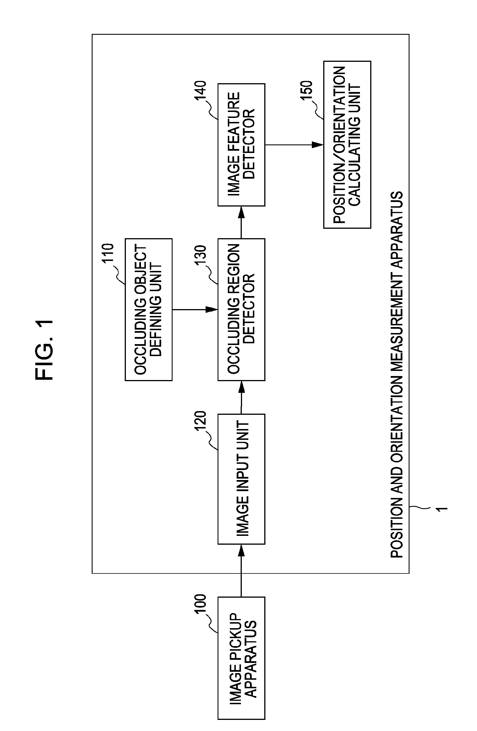
[0058]FIG. 1 shows an example structure of a position and orientation measurement apparatus 1 according to the first embodiment. As shown in FIG. 1, the position and orientation measurement apparatus 1 includes an occluding object defining unit 110, an image input unit 120, an occluding region detector 130, an image feature detector 140, and a position / orientation calculating unit 150. An image pickup apparatus 100 is connected to the image input unit 120.

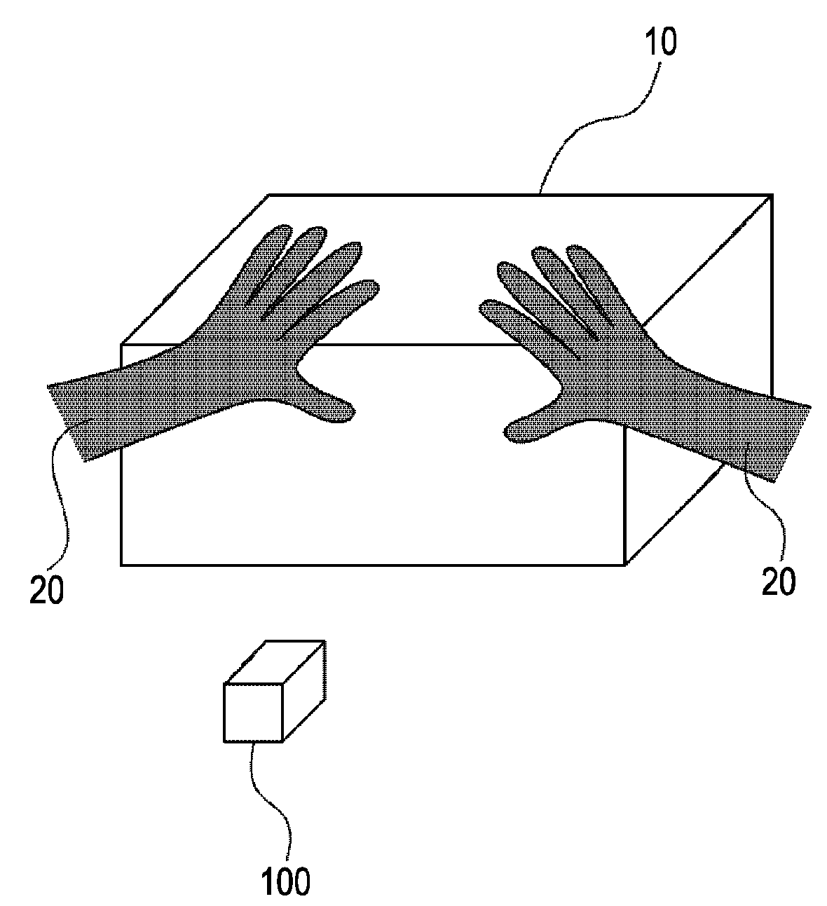
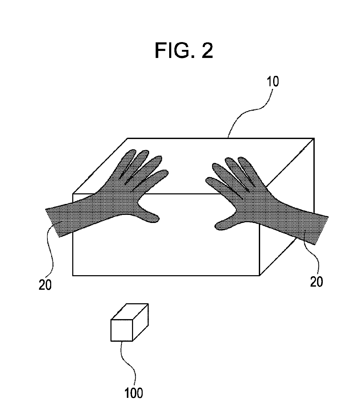
[0059]FIG. 2 is a diagram showing a typical situation where the posit...

modification example of first embodiment

[0106]In the first embodiment, an object occluding an observation target object is a hand but is not limited thereto, and may be any other object having features on a two-dimensional image, such as a face.

[0107]For example, as shown in FIG. 12, a database of face images is determined in advance, and a captured image is matched with the face images in the database. It is determined that a region of the image matched with the face images is occluded by a face, and no image features are detected in that region. With this method, stable high-accuracy position and orientation calculation can be achieved.

[0108]In the first embodiment, an occluding region is detected on the basis of the color of a hand. If an occluding object has a unique color, an occluding region may be detected on the basis of the unique color. For example, when a user wears orange-colored gloves on his / her hands, an orange-colored region in a captured image may be detected as an occluding region.

[0109]Alternatively, an...

second embodiment

[0110]In the first embodiment, a hand region is detected on a captured image and is designated as an occluding region. No image features are detected in the occluding region, thereby achieving stable high-accuracy calculation of the position and orientation of an observer relative to an observation target object.

[0111]In a second embodiment of the present invention, an occluding region is not detected using features on a two-dimensional image in the manner described in the first embodiment, but is detected from a captured image using a model of an occluding object and the rough position and orientation of the occluding object and an image pickup apparatus.

[0112]FIG. 13 shows an example structure of a position and orientation measurement apparatus 2 according to the second embodiment. As shown in FIG. 13, an image pickup apparatus 100 is connected to the position and orientation measurement apparatus 2. The position and orientation measurement apparatus 2 includes an occluding object...


PUM


Abstract

In position and orientation measurement based on natural features, erroneous detection of the natural features is prevented when an observation target object is occluded by another object, and registration stability is improved. To this end, an occluding object that can occlude the observation target object is defined, and an occluding region where the occluding object occludes the observation target object is detected in an input captured image. Image features of the observation target object are detected in a region of the captured image other than the detected occluding region. Therefore, the position or orientation of an image pickup apparatus that captured the captured image, or the position or orientation of the observation target object in the captured image are calculated.

Description

BACKGROUND OF THE INVENTION[0001]1. Field of the Invention[0002]The present invention relates to a technique for calculating at least one of the position and orientation of an image pickup apparatus or an observation target object on the basis of image features detected on a captured image.[0003]2. Description of the Related Art[0004]Recently, research of Mixed Reality (MR) techniques for providing a seamless integration of real and virtual spaces has been actively conducted. Among these MR techniques, especially an Augmented Reality (AR) technique that superimposes a virtual space on a real space has received attention.[0005]An image providing apparatus employing the AR technique is mainly implemented by a video see-through or optical see-through head mounted display (HMD).[0006]In a video see-through HMD, a virtual-space image (e.g., virtual objects or text information rendered by computer graphics) generated according to the position and orientation of an image pickup apparatus s...

Claims


Application Information

Patent Timeline
Patent Type & Authority Applications(United States)
IPC IPC(8): H04N5/228
CPCG06K9/3216G06V10/245
Inventor KOTAKE, DAISUKENAKAZAWA, TOSHIHIROSUZUKI, MASAHIROTAKEMOTO, RIKASATOH, KIYOHIDEIWASE, YOSHIHIKO
Owner CANON KK
Why Eureka
Try Eureka