
Method and apparatus for magnetic character recognition

a magnetic character and recognition method technology, applied in the field of magnetic character recognition methods and apparatuses, can solve the problems of false recognition, poor printing of magnetic ink, and impaired accuracy of magnetic character recognition, and achieve high accuracy, high coincidence, and high comparison

Active Publication Date: 2008-11-20
SANKYO SEIKI MFG CO LTD
View PDF6 Cites 6 Cited by
  • Summary
  • Abstract
  • Description
  • Claims
  • Application Information

AI Technical Summary

Benefits of technology

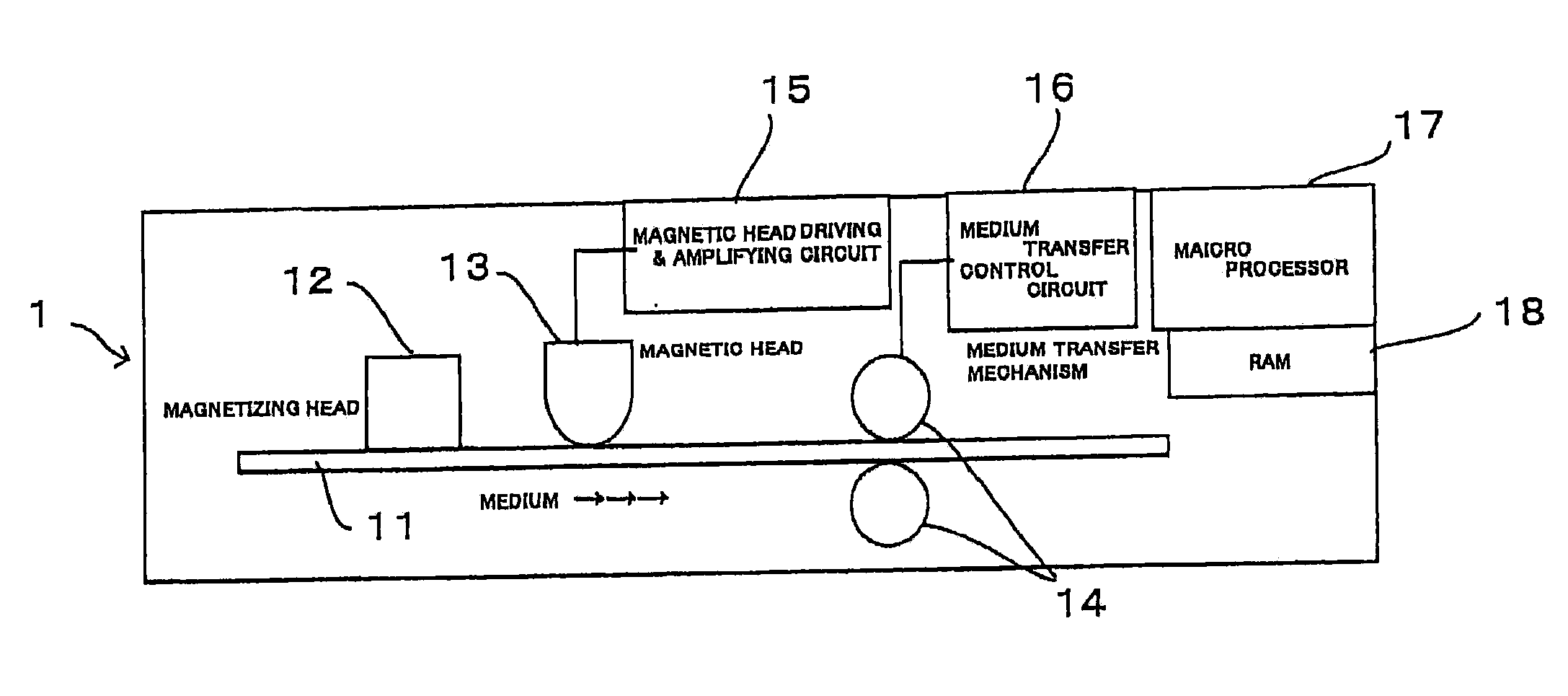
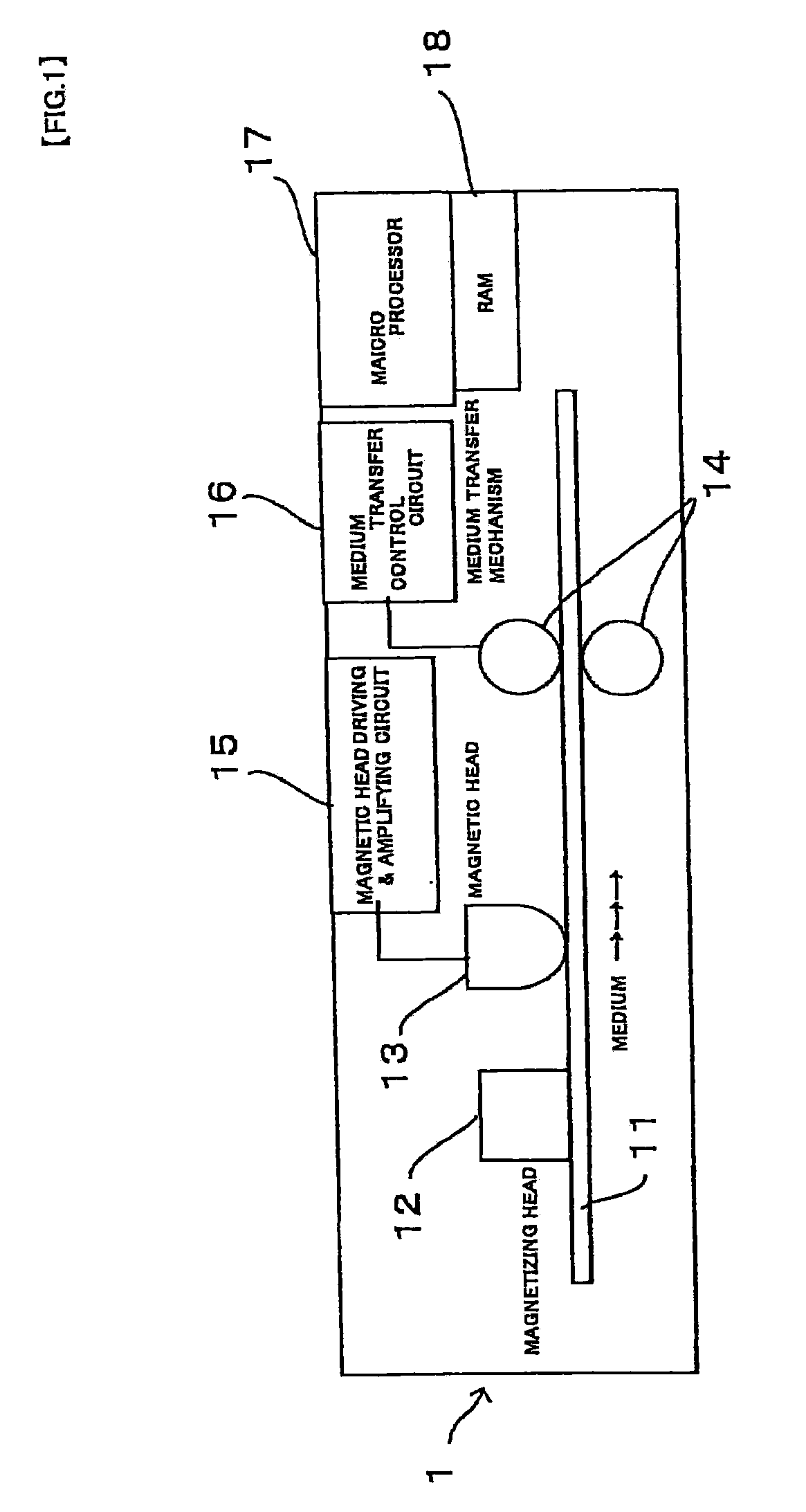
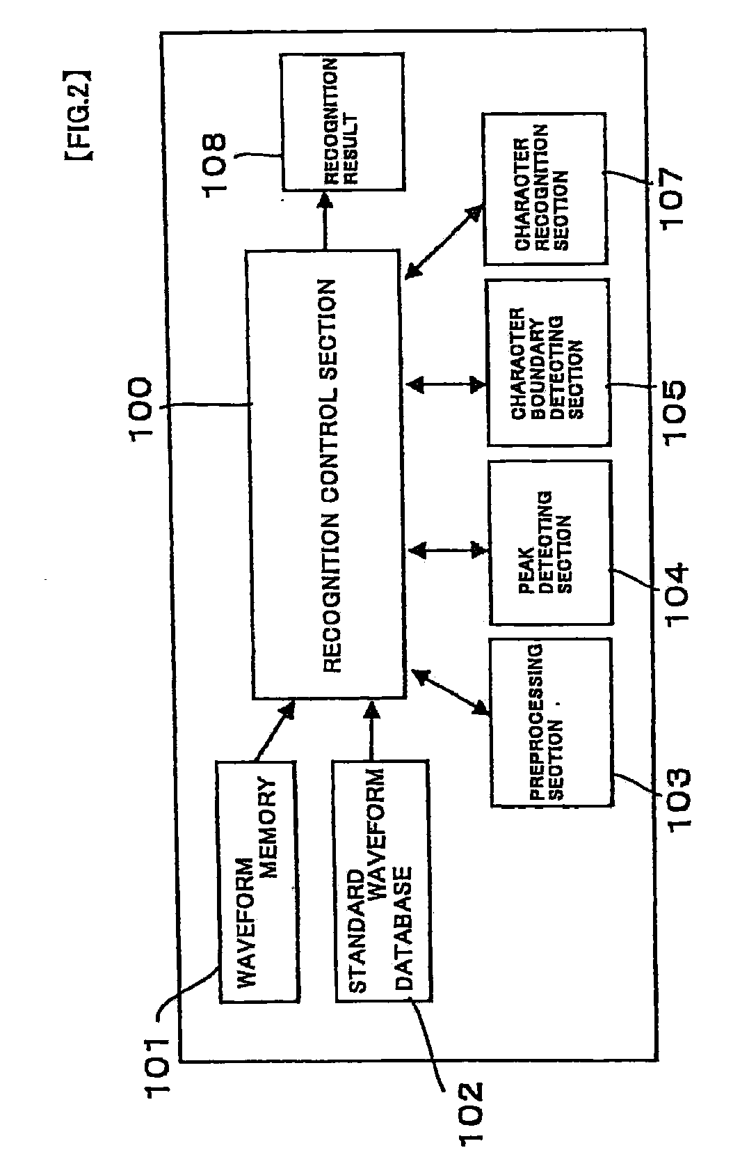
[0016]According to at least an embodiment of the present invention; standard array data of peak intervals is prepared at first out of an array pattern of a plurality of intervals between peaks that are included in a standard character waveform of each magnetic character. Subsequently, a regeneration waveform is generated out of a character string of magnetic characters, and a character waveform of each magnetic character is segmented. Then, array data of peak intervals is generated out of an array pattern of a plurality of intervals between peaks that are included in the character waveform, and the array data of peak intervals is compared with the standard array data of peak intervals. As a result, a read character is identified with a character corresponding to an array data of peak intervals that shows the highest coincidence. Therefore, the magnetic character recognition can be carried out with high accuracy.
[0037]According to at least an embodiment of the present invention, a read character is identified with a character corresponding to an array data of peak intervals that shows high coincidence in comparison between the array data of peak intervals and standard array data of peak intervals. Therefore, magnetic character recognition can be carried out with high accuracy even when there exists deformation in the magnetic waveform pattern. Particularly, when the array data of peak intervals is generated, an adjustment is so made as to equalize the number of peaks included in the character waveform and the standard number of peaks included in the standard character waveform; and therefore the character recognition can be carried out, being unlikely to get influenced by damage on peaks due to a void, spot, etc., and / or waveform deformation due to a quasi peak.

Problems solved by technology

However, among checks and so on used practically in the marketplace, some include poorly printed magnetic ink characters even though the characters are still within an allowable range.
Particularly, if the check has been stored while being folded, width and intervals of the characters become altered when a folded part is scanned so that accuracy of the magnetic character recognition may be impaired.
However, those methods are likely to make a misjudgment and probably lead to false recognition when the peak interval in the magnetic waveform is sized around the middle between a wide interval and a narrow interval.

Method used


Image

  • Method and apparatus for magnetic character recognition
  • Method and apparatus for magnetic character recognition
  • Method and apparatus for magnetic character recognition

Examples


first embodiment

[0084]Subsequently, character recognition is carried out (Step S5 in FIG. 3).

[0085]FIG. 7A is a flowchart showing a detailed workflow of the character recognition (Step S5) described in the flowchart of FIG. 3. Meanwhile, FIG. 8 is an example of a line of magnetic characters printed on a medium such as a check. The magnetic pattern is read in a direction from the right to the left in FIG. 8. The waveforms of magnetic regeneration signals read in such a manner are processed through the steps of the character segmentation described above. As a result, array data of the distances between neighboring two peaks shown below in “(Table 1)” is acquired (Step S31).

TABLE 16543211D16D15D14D13D12D112D26D25D24D23D22D213D36D35D34D33D32D31.....................lDi6Di5Di4Di3Di2Di1.....................nDn6Dn5Dn4Dn3Dn2Dn1

[0086]Subsequently, for each character, the array data of the distances between neighboring two peaks is sequentially compared with each of an array data of a template (Standard array...

second embodiment

[0096]Character recognition according to a second embodiment is described below next. Being provided with operations from Step S37 through Step S41 before those from Step S31 through Step S36 described above, the second embodiment ensures the character recognition with high accuracy even when there exists a low level of peak output in the regeneration waveform due to a void and / or waveform deformation due to a quasi peak.

Subsequently, the character recognition is carried out (Step S5 in FIG. 3).

[0097]FIG. 7B is a flowchart showing a detailed workflow of the character recognition (Step S5) described in the flowchart of FIG. 3. Meanwhile, FIG. 8 is an example of a line of magnetic characters printed on a medium such as a check. The magnetic pattern is read in a direction from the right to the left in FIG. 8. The waveforms of magnetic regeneration signals read in such a manner are processed through the steps of the character segmentation described above. As a result, array data of the ...


PUM


Abstract

A method for magnetic character recognition may include preparing standard array data of peak intervals; generating a regeneration waveform out of a character string of magnetic characters printed on a surface of an information data recording medium; segmenting a character waveform of each magnetic character out of the regeneration waveform; generating array data of peak intervals out of an array pattern of a plurality of intervals between peaks that are included in the character waveform; and comparing the array data of peak intervals with the standard array data of peak intervals; wherein, based on a comparison result of comparing the array data of peak intervals with the standard array data of peak intervals, a read character is identified with a character corresponding to an array data of peak intervals that shows the highest coincidence.

Description

CROSS REFERENCE TO RELATED APPLICATIONS[0001]The present application claims priority under 35 U.S.C. § 119 to Japanese Application No. 2007-131232 filed on May 17, 2007 and Japanese Application No. 2008-007657 filed on Jan. 17, 2008, the contents of both of which are incorporated herein by reference.FIELD OF THE INVENTION[0002]The present invention relates to a method and an apparatus for magnetic character recognition for reading a character string printed with magnetic ink characters and generating a regeneration waveform for character recognition, and particularly to a method and an apparatus thereof that enables character recognition with high accuracy.BACKGROUND[0003]Conventionally, there have been disclosed various methods in which a part of a medium surface, where magnetic ink characters (MICR characters) are printed, is read by using a magnetic head so as to obtain a magnetic regeneration signal for the purpose of character recognition. The magnetic ink characters (MICR char...

Claims


Application Information

Patent Timeline
Patent Type & Authority Applications(United States)
IPC IPC(8): G06K9/00
CPCG06K7/084G06K9/186G07D7/04G07D7/0047G06V30/2253
Inventor NAKAMURA, HIROSHI
Owner SANKYO SEIKI MFG CO LTD
Learn More