
Image forming apparatus and control device

Inactive Publication Date: 2008-11-20
KYOCERA DOCUMENT SOLUTIONS INC
View PDF3 Cites 6 Cited by
  • Summary
  • Abstract
  • Description
  • Claims
  • Application Information

AI Technical Summary

Benefits of technology

[0012]It is an object of the present invention to provide an image forming apparatus which is capable of detecting the moving speed or meandering of a revolving endless belt with high accuracy, and thereby which can prevent the color shift while permitting cost reduction. It is another object of the present invention to provide a control device which is capable of detecting the moving speed or meandering of the revolving endless belt with high accuracy.
[0015]As a result, either of the moving speed and the amount of meandering of the endless belt can be detected with high accuracy. Therefore, the color shift in the circumferential direction of the endless belt and in the direction perpendicular to the circumferential direction can be reliably prevented. Moreover, since either of the moving speed and the amount of meandering of the endless belt can be detected with one detection unit having the emission part and the image receiving part, the cost of the image forming apparatus can be reduced.
[0018]According to this configuration, traveling of the endless belt is adjusted into a non meandering state when the image forming apparatus is manufactured. With this point in time as a reference, the amount of meandering calculated by the control part is accumulated every time the endless belt is driven. When the accumulated amount of meandering stored in the storage part exceeds the predetermined range, the traveling of the endless belt is controlled by the control part so as to correct the meandering of the endless belt. As a result, an image forming apparatus can easily be realized which can prevent the color shift in the direction perpendicular to the circumferential direction of the endless belt.
[0019]In the image forming apparatus with the configuration described above, a rear surface of the endless belt is irradiated with light by the emission light, and the successive images of the rear surface of the endless belt are obtained by the image receiving part. As a result, the successive images can be easily compared with one another. Therefore, even in a case where it is difficult to compare the successive images with one another since the surface of the endless belt is formed of a gross surface, the moving speed or the meandering can be detected easily.

Problems solved by technology

However, with the former image forming apparatus, when slipping occurs between the intermediate transfer body and the driving roller, the moving speed of the intermediate transfer body is erroneously detected.
Moreover, when the intermediate transfer body and the driving roller wear due to a sliding therebetween, a difference arises between the moving speed obtained from the rotation angle of the driving roller and an actual moving speed.
With these circumstances, the accuracy in detecting the moving speed of the intermediate transfer body deteriorates.
Thus, there has arisen a problem that the moving speed of the intermediate transfer body cannot be controlled with high accuracy, thus resulting in failure to satisfactorily prevent the color shift in the circumferential direction.
With these circumstances, there has also arisen a problem that meandering of the intermediate transfer body cannot be detected with high accuracy, thus resulting in failure to satisfactorily prevent the color shift in the direction perpendicular to the circumferential direction.
Therefore, there has arisen a problem that cost of the image forming apparatus increases.
The same problem arises in an image forming apparatus that conveys a recording sheet by an endless belt revolving in such a manner as to oppose a photoconductive drum and then transfers a toner image onto the recording sheet directly from the photoconductive drum.

Method used


Image

  • Image forming apparatus and control device
  • Image forming apparatus and control device
  • Image forming apparatus and control device

Examples


Embodiment Construction

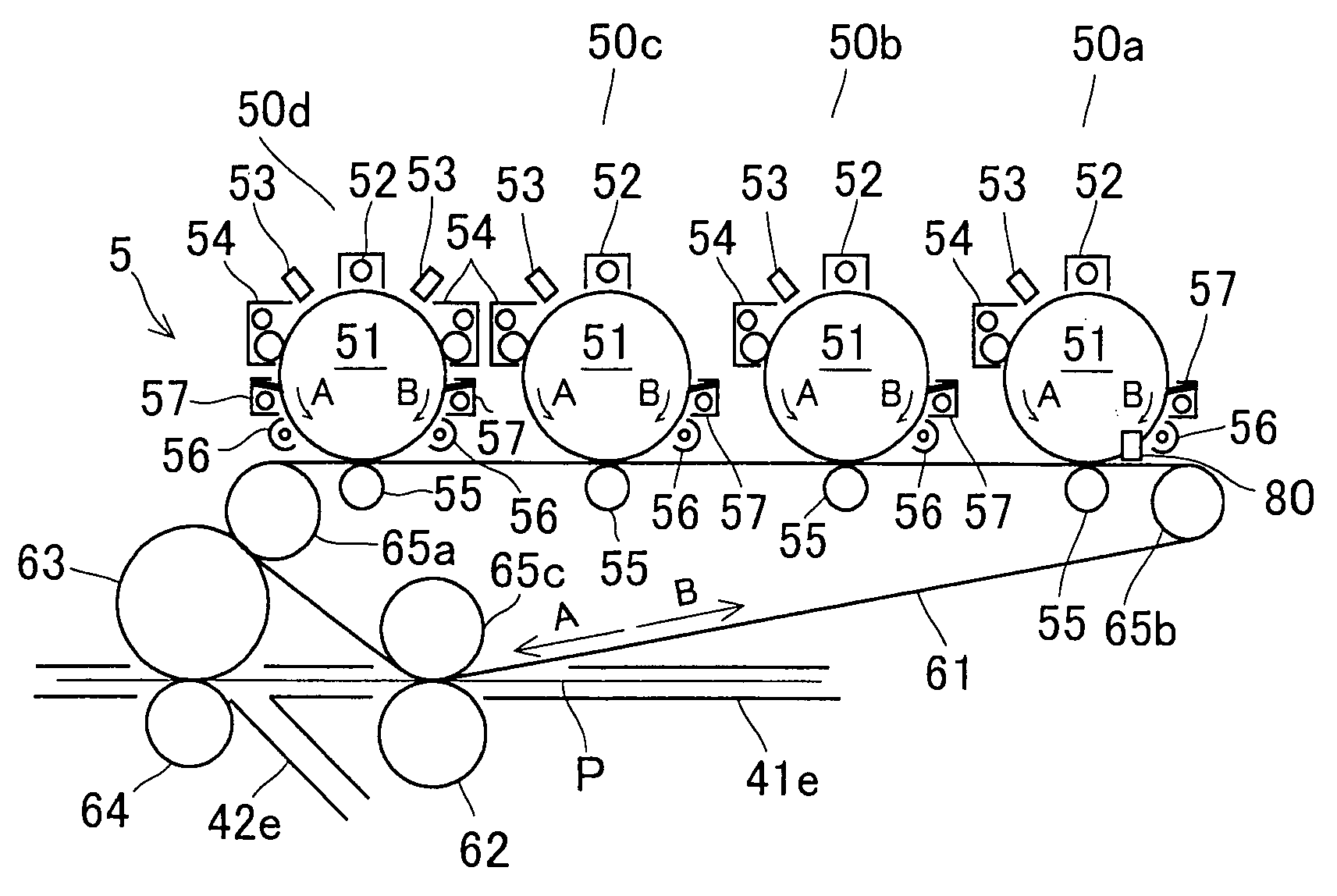
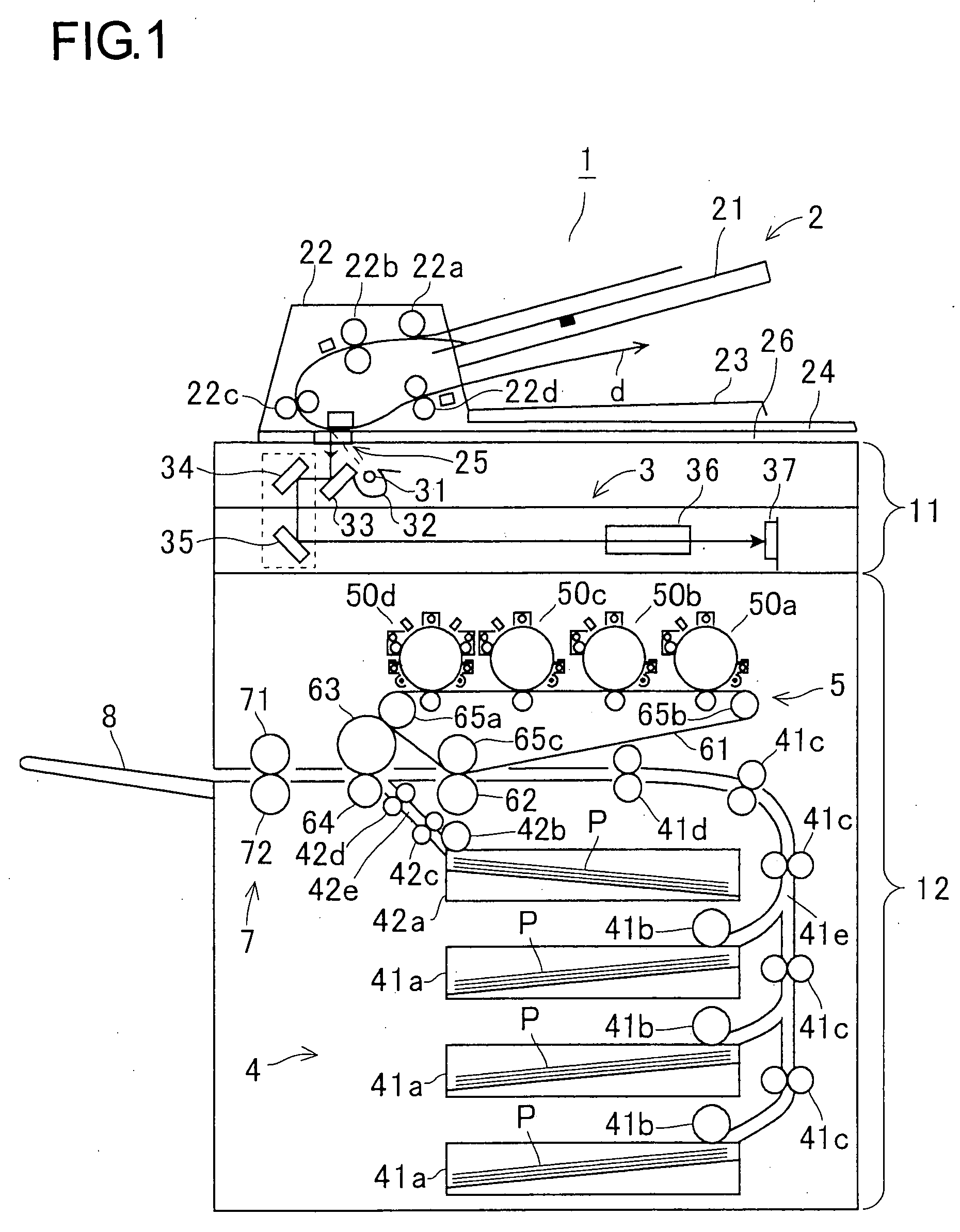
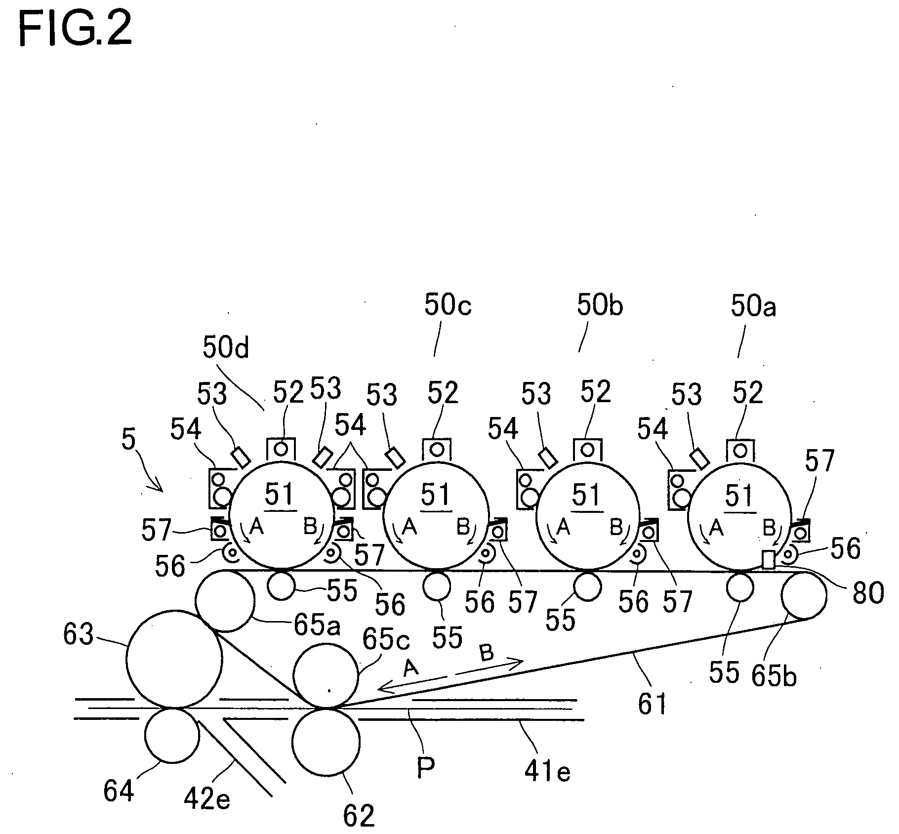
[0029]Hereinafter the embodiments of the present invention will be described with reference to the accompanying drawings. FIG. 1 is an elevation view to show a schematic configuration of an image forming apparatus according to a first embodiment. The image forming apparatus 1 is formed of a color copier, and has an upper housing 11 and a lower housing 12. On the upper housing 11, a document conveyance part 2 for conveying a document is mounted in such a manner as to be capable of opening and closing with a support provided at a rear part thereof.

[0030]The document conveyance part 2 includes a document feed tray 21, a document conveyance part main body 22, a document discharge tray 23, and a document cover 24. On the document feed tray 21, a document is loaded. The document conveyance part main body 22 conveys the document fed from the document feed tray 21 for scanning. The document discharge tray 23 stores the document discharged from the document conveyance part main body 22. The ...


PUM


Abstract

A low cost image forming apparatus capable of detecting a moving speed or meandering of a revolving endless belt with high accuracy to thereby prevent the color shift includes: a revolving endless belt sequentially superimposing and transferring toner images formed on a plurality of photoconductive drums directly thereon or onto a recording sheet conveyed thereby; an emission part irradiating light to the endless belt; an image receiving part receiving light reflected on the endless belt to obtain successive images of the endless belt; and a control part comparing the successive images obtained by the image receiving part with one another, calculating either of a moving speed and an amount of meandering of the endless belt, and correcting either of the moving speed and the meandering of the endless belt based on a result of the calculation.

Description

[0001]This application is based on Japanese Patent Application No. 2006-316681 filed on Nov. 24, 2006, the contents of which are hereby incorporated by reference.BACKGROUND OF THE INVENTION[0002]1. Field of the Invention[0003]The present invention relates to an image forming apparatus provided with an endless belt revolving in such a manner as to oppose a plurality of photoconductive drums. The present invention also relates to a control device that controls speed or meandering of a revolving, endless object to be measured.[0004]2. Description of Related Art[0005]A conventional image forming apparatus is disclosed in JP-A-2001-083761. This image forming apparatus includes a plurality of photoconductive drums, and an intermediate transfer body formed of an endless belt revolving in such a manner as to oppose the plurality of photoconductive drums. Toner images formed on the respective photoconductive drums are superimposed on one another and transferred onto the intermediate transfer...

Claims


Application Information

Patent Timeline
IPC IPC(8): G03G15/16
CPCG03G2215/00139G03G2215/00143G03G2215/00156G03G15/0194G03G2215/0158G03G15/1615G03G2215/0129
Inventor TAMURA, YOSHIAKI
Owner KYOCERA DOCUMENT SOLUTIONS INC
Learn More