
Method for implementing concurrent producer-consumer buffers

a buffer and producer technology, applied in the field of computer systems, can solve the problems of both putters and takers acquiring both locks

Inactive Publication Date: 2008-11-20
IBM CORP
View PDF10 Cites 14 Cited by
  • Summary
  • Abstract
  • Description
  • Claims
  • Application Information

AI Technical Summary

Problems solved by technology

A significant source of contention and high latency in this implementation is that both putters and takers acquire both locks even when the buffer is neither empty nor full.

Method used


Image

  • Method for implementing concurrent producer-consumer buffers
  • Method for implementing concurrent producer-consumer buffers
  • Method for implementing concurrent producer-consumer buffers

Examples


Embodiment Construction

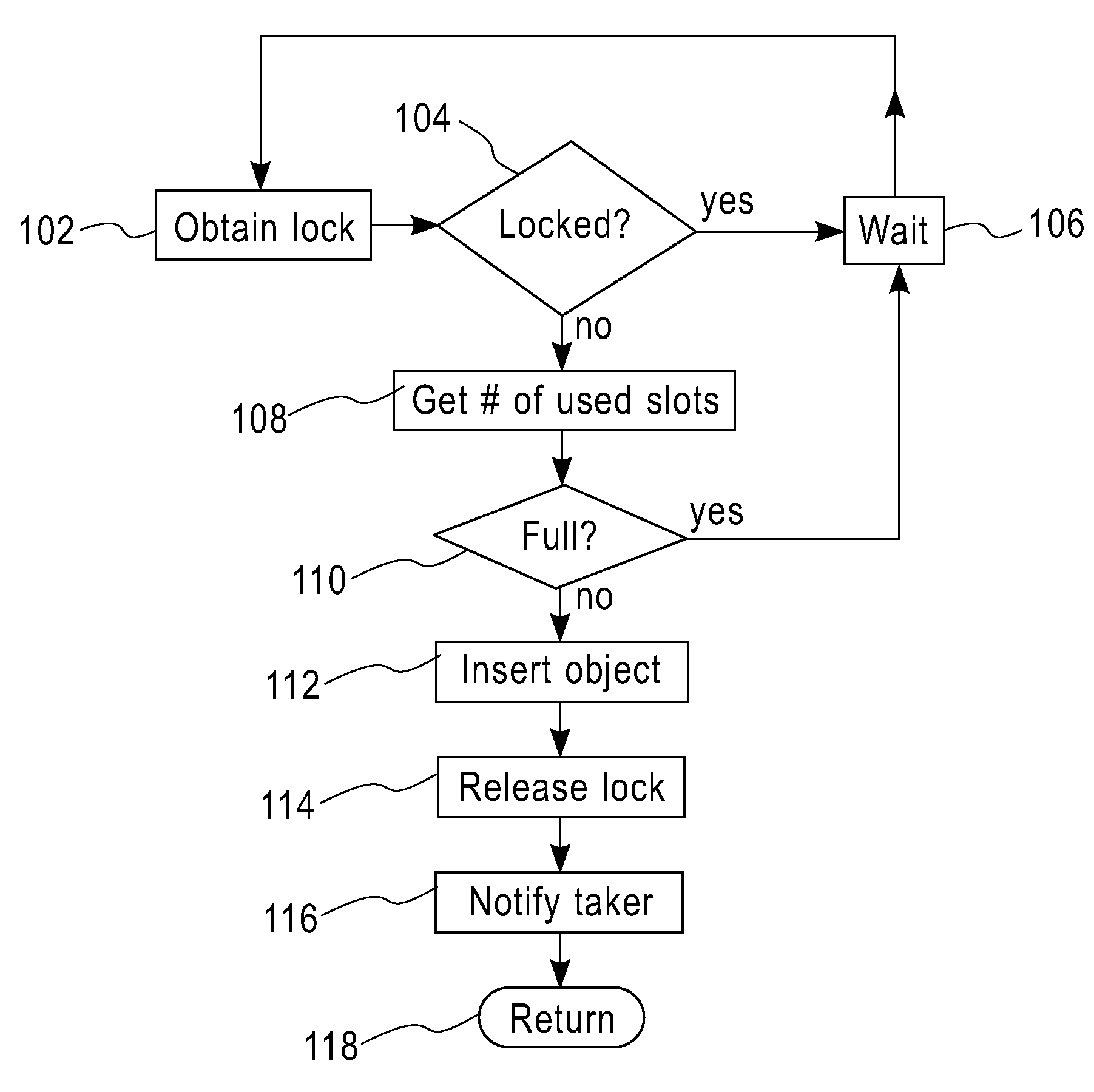
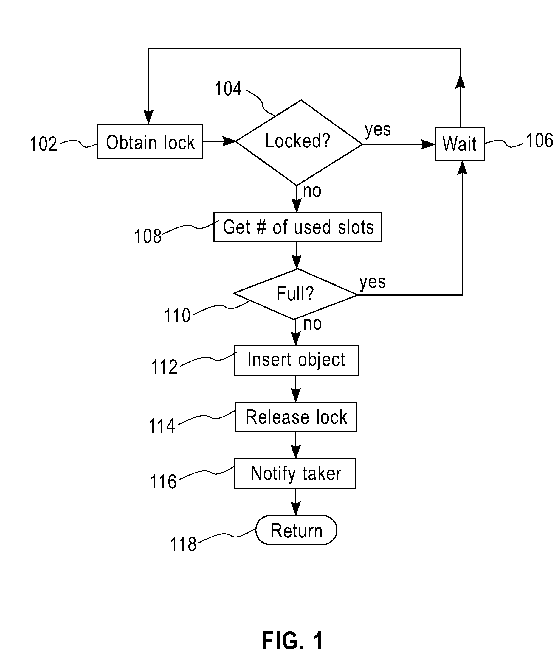
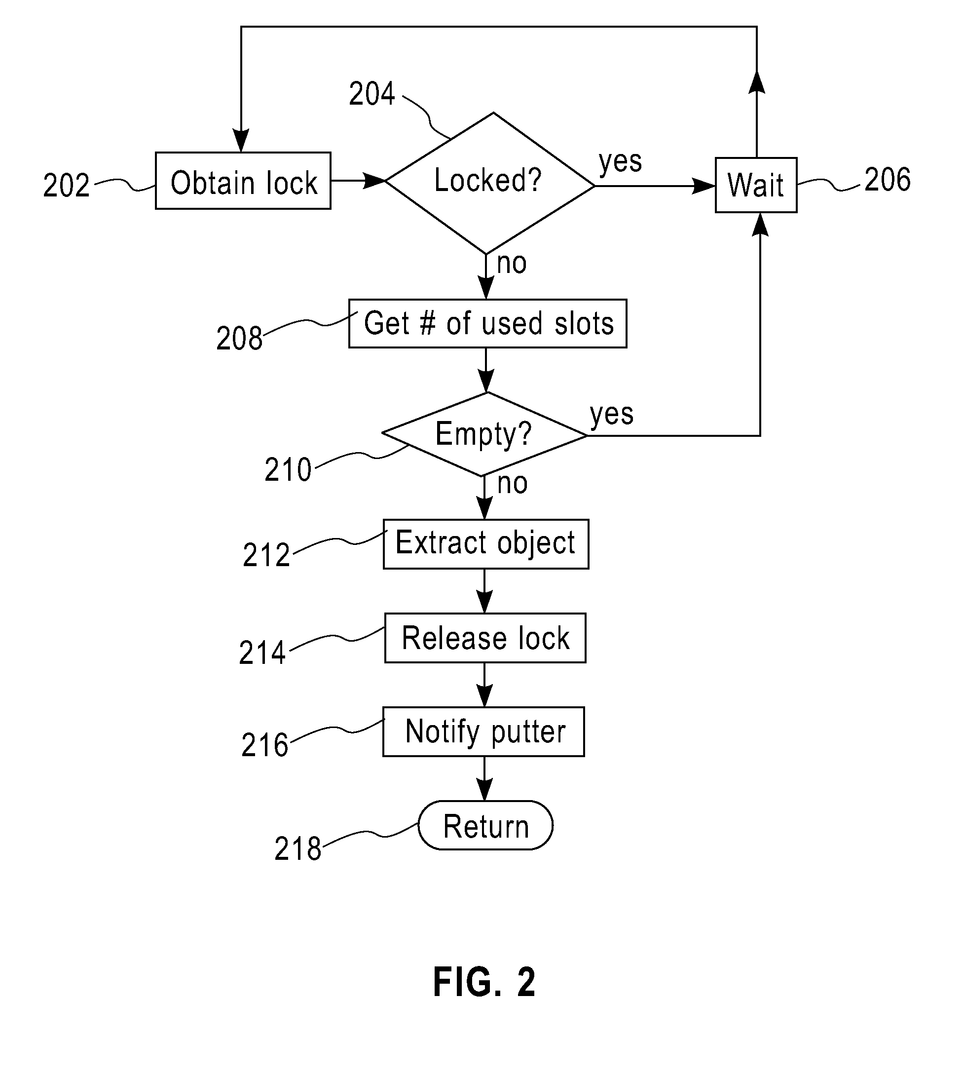
[0016]A method and system for providing novel design for buffer structure that, for example, reduces latency and contention on the buffer's lock structures are provided. In one embodiment, the method and system of the present disclosure enables producers to operate using one lock on one side of a buffer, while consumers operate on the other side of the buffer using a separate lock. Buffer size may be implemented as a lock-free AtomicInteger, supported in Java JDK 5.0 or simulated using a dedicated lock which is separate from the aforementioned locks guarding the operations on either side of the buffer. When the buffer is neither full nor empty, producers and consumers uses one lock acquisition and release, and neither producers nor consumers are blocked by each other. In one embodiment, the two main locks are always flat (also referred to as deflated). That is, the two main locks are not used for wait-notify, for instance. Such mechanism reduces the latency of their acquisition and ...


PUM


Abstract

A method and a system for implementing concurrent producer-consumer buffers are provided. The method and system in one aspect uses separate locks, one for putter and another for taker threads operating on a concurrent producer-consumer buffer. The locks operate independently of a notify-wait process.

Description

FIELD OF THE INVENTION[0001]The present application relates generally to computer systems and, particularly to a method and system for implementing concurrent producer-consumer buffers.BACKGROUND OF THE INVENTION[0002]In multithreaded programs, several threads can be involved in the processing of a single request and a bounded buffer instance can serve to decouple the operation of threads with different roles in the request handling. For example, few (for example, one to three) threads poll requests from a network socket and insert them at one end into a bounded buffer. These threads are referred to as “putters.” At the other end of the buffer, a plurality of worker threads take requests from the buffer and service them. These threads are referred to as “takers.”[0003]For example, a bounded buffer may be implemented as a circular array with two indices, takeIndex and putIndex, and two counters, numberOfUsedSlots and numberOfEmptySlots. The two counters indicate to takers and putters...

Claims


Application Information

Patent Timeline
Patent Type & Authority Applications(United States)
IPC IPC(8): G06F17/30
CPCG06F9/526G06F9/544
Inventor DUGGIRALA, SURYA V.MICHAEL, MAGED M.PRAUN, CHRISTOPH VON
Owner IBM CORP
Learn More