Device and Method for Coupling a Vessel to a Stationary Object

a technology for coupling devices and objects, applied in transportation and packaging, bridges, passenger handling devices, etc., can solve problems such as difficult placement of coupling elements around pipes, and achieve the effect of preventing or limited damage to devices

Active Publication Date: 2008-11-27
AMPELMANN HLDG BV
View PDF13 Cites 10 Cited by
  • Summary
  • Abstract
  • Description
  • Claims
  • Application Information

AI Technical Summary

Benefits of technology

[0012]According to a further improvement, the device is designed such that said control means comprise a second sensor for detecting a loading and/or overloading of said clamp. This means that the loading and/or overloading of the construction is known in the control system and that measures can be taken if necessary. The result is that damage to the device can be prevented or limited.
[0013]According to a further improvement, the device is designed such that said control means are designed for opening said clamp and/or switching on said first drive means after a detection of overloading of said clamp. This means that in the event of overloading damage is prevented, and also that on uncoupling of the gangplank from the pipe the gangplank drops down.
[0014]According to a further improvement, the device is designed such that said coupling element and said gangplank are designed in such a way that a coupled pipe, measured parallel to said top s

Problems solved by technology

The disadvantage of the known device is that placing the coupling element around the pipe is difficult because the coupling elem

Method used


Image

  • Device and Method for Coupling a Vessel to a Stationary Object
  • Device and Method for Coupling a Vessel to a Stationary Object
  • Device and Method for Coupling a Vessel to a Stationary Object

Examples


Embodiment Construction

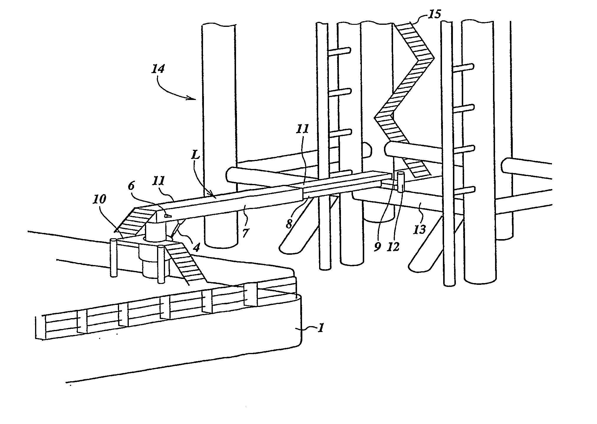
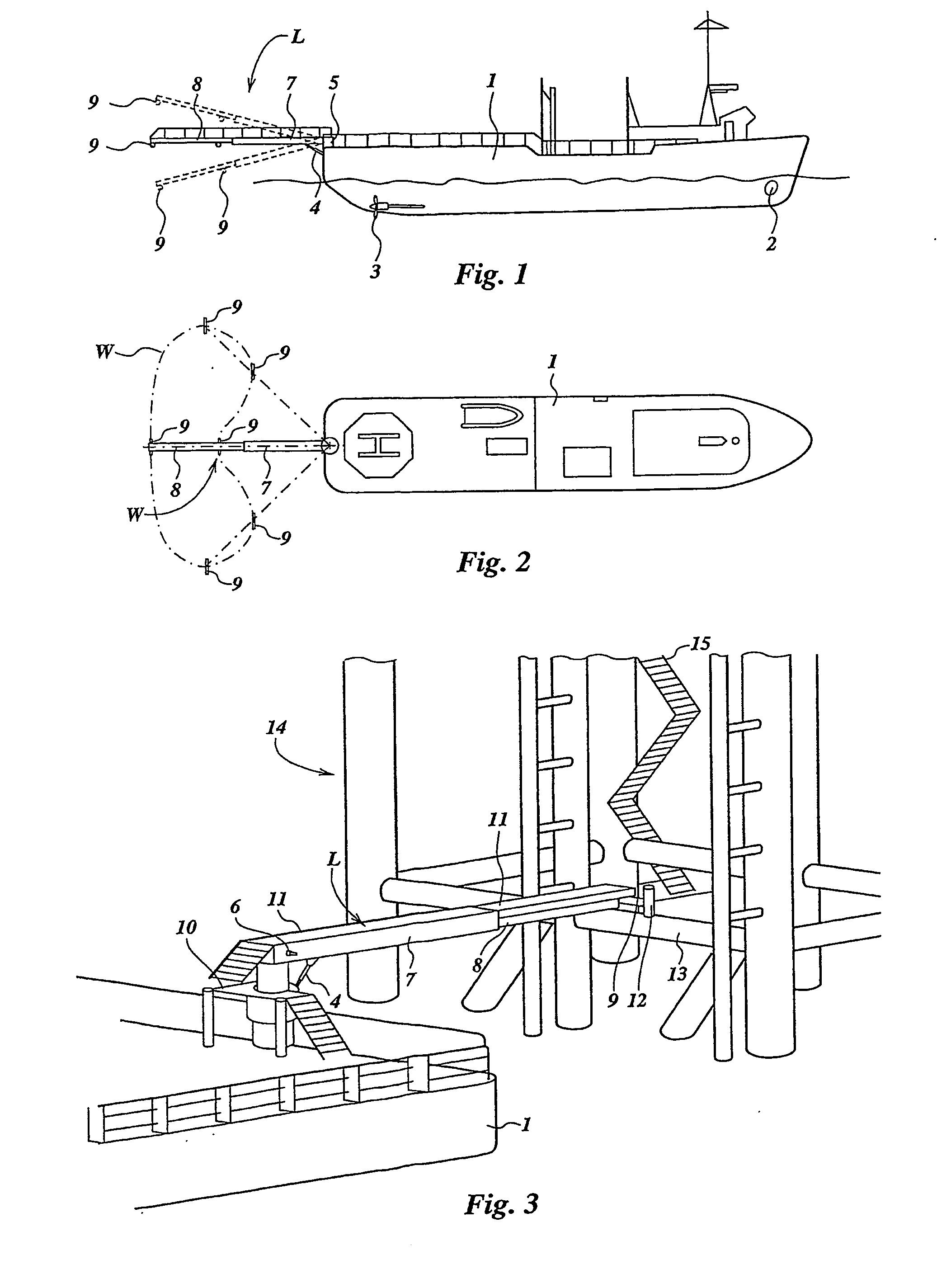
[0029]FIGS. 1 and 2 show a vessel 1 with a propulsion system consisting of, inter alia, propellers 3 and a bow thruster 2. A pivot point 5, to which a gangplank L is attached, is provided on the stem of the vessel 1, which gangplank has a first gangplank part 7 and a second gangplank part 8 which telescopes into said first gangplank part. The first gangplank part 7 is attached to the pivot point 5 by means of a pivot pin 6 and can be moved in the vertical plane by a lifting cylinder 4. By means of a drive (not shown) the gangplank L can rotate about a vertical axis of the pivot point 5, with the result that the gangplank L can be laid on the afterdeck of the vessel 1 during transport. During use the gangplank L is moved to a position behind the vessel 1.

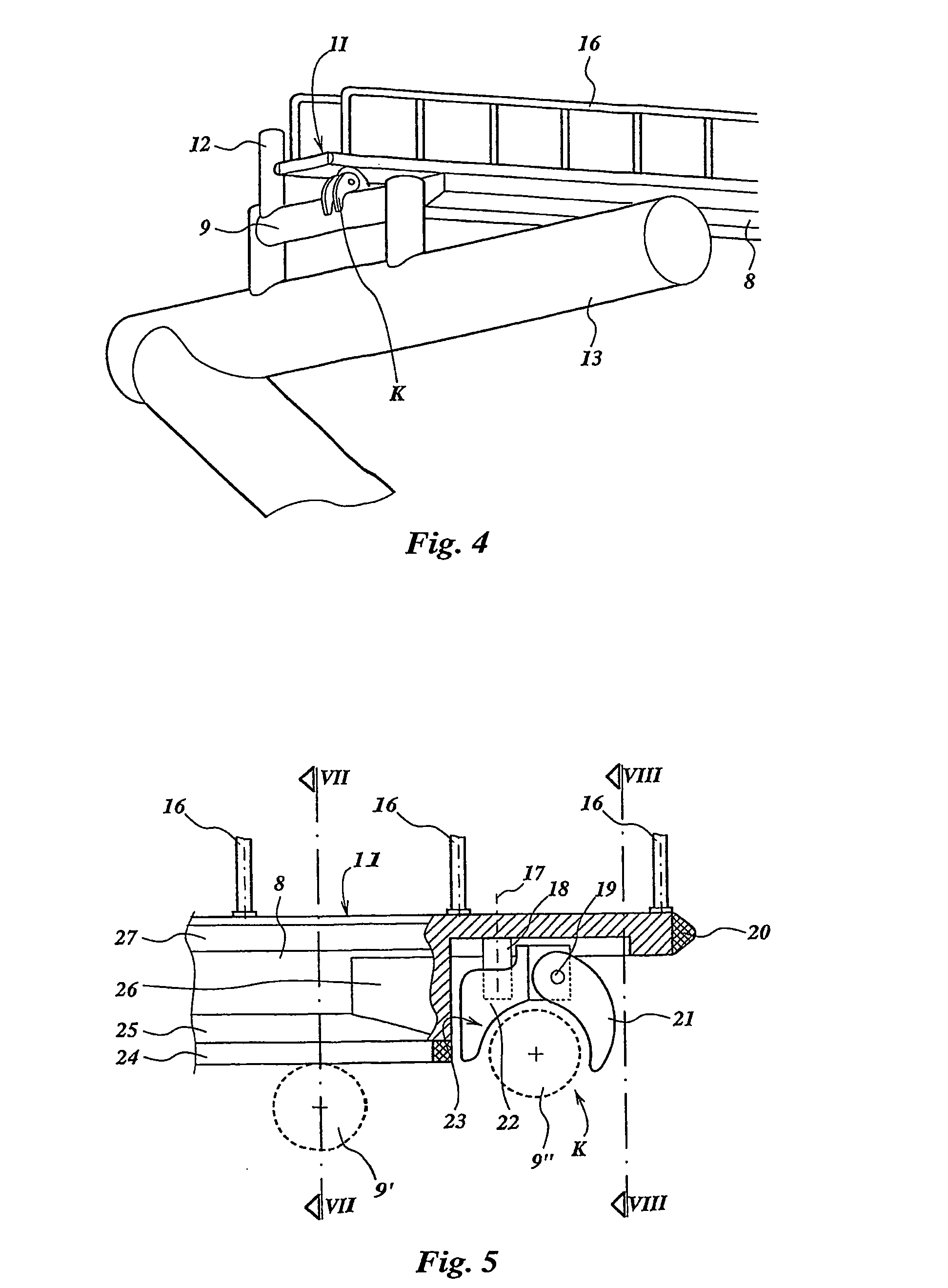
[0030]The end of the second gangplank part 8 is provided, in a manner to be indicated below, with coupling means K, by means of which the gangplank L can be coupled to a coupling pipe 9, which forms part of a stationary object 14 pla...


PUM


Abstract

The invention relates to a device for making a walkway from a vessel to an object which is more or less stationary relative to the vessel and has a gangplank attached to the vessel. The gangplank has a top surface and near the end of the gangplank a coupling element for enclosing a horizontal pipe attached to the stationary object. According to the invention, the coupling element is fitted below the top surface, and near the coupling element on the underside in the longitudinal direction of the gangplank the gangplank has a narrow supporting edge for supporting the gangplank on the pipe. The invention also comprises a method for the use of the device.

Description

CROSS-REFERENCE TO RELATED APPLICATIONS[0001]This application is the National Stage of International Application No. PCT / NL2005 / 000255, filed Apr. 5, 2005, which claims the benefit of Netherlands Application No. 1025923, filed Apr. 9, 2004, the contents of which are incorporated by reference herein.FIELD OF THE INVENTION[0002]The invention relates to a device for coupling a vessel to a stationary object.BACKGROUND OF THE INVENTION[0003]Such a device is known from WO 0220343. The disadvantage of the known device is that placing the coupling element around the pipe is difficult because the coupling element keeps constantly moving under the influence of waves and it is difficult for the drive means to compensate for this movement.SUMMARY OF THE INVENTION[0004]In order to avoid this disadvantage, the present invention provides a device for making a walkway from a vessel to an object which is more or less stationary relative to said vessel, comprising a telescopingly extendable gangplank...

Claims


Application Information

Patent Timeline
IPC IPC(8): B63B27/14E01D15/14
CPCB63B27/143
Inventor STAPEL, HENDRIK PIETER
Owner AMPELMANN HLDG BV
Why Eureka
Try Eureka