Petroleum viscosity measurement and communication system and method

a technology of viscosity measurement and communication system, which is applied in the field of system and method for measuring viscosity of liquid, can solve the problems of unreliable, bulky sensors, and methods, and achieve the effects of reducing the number of sensors

Inactive Publication Date: 2008-11-27
RICHMOND CHEM CORP
View PDF99 Cites 31 Cited by
  • Summary
  • Abstract
  • Description
  • Claims
  • Application Information

AI Technical Summary

Benefits of technology

[0017]In a further embodiment, the apparatus can have a network interface for interfacing with a communication network, such as the Internet, for receiving the lubricating oil quality signal and for transmitting the lubricating oil quality signal to the communications network. The user interface device, such as a PDA having a wireless interface and supporting software for interfacing and communicating with the communications network, can receive the lubricating oil quality signal from the communication network and communicate the lubricating oil quality signal through the interface, such as through a display screen.
[0018]The lubricating oil quality signal, value and/or information displayed or communicated to a driver or user can include various significant information. Specifically, the lubricating oil quality information can include “change oil now” information, information regarding the time until an oil change is needed, information regarding the driving distance until an oil change is needed, viscosity information, service station information, and/or coupon information,...

Problems solved by technology

The above systems, apparatuses, and methods include bulky sensors which are sometimes unreliable, in part due to the limited information which such sensors are able to provide for determining related parameters.
These mechanisms and parameters are a product of the measured or sensed information and thus have inherent potential drawbacks associated with such measu...

Method used


Image

  • Petroleum viscosity measurement and communication system and method
  • Petroleum viscosity measurement and communication system and method
  • Petroleum viscosity measurement and communication system and method

Examples


Embodiment Construction

[0049]While this invention is susceptible to embodiment in many different forms, there are shown in the drawings and herein described in detail preferred embodiments with the understanding that the present disclosure is considered to provide an example of the principles of the invention, and is not intended to limit the broad aspect of the invention to the embodiments illustrated.

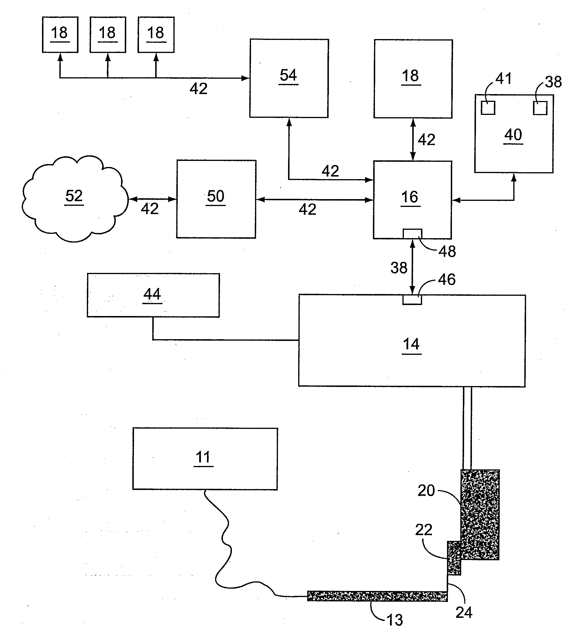
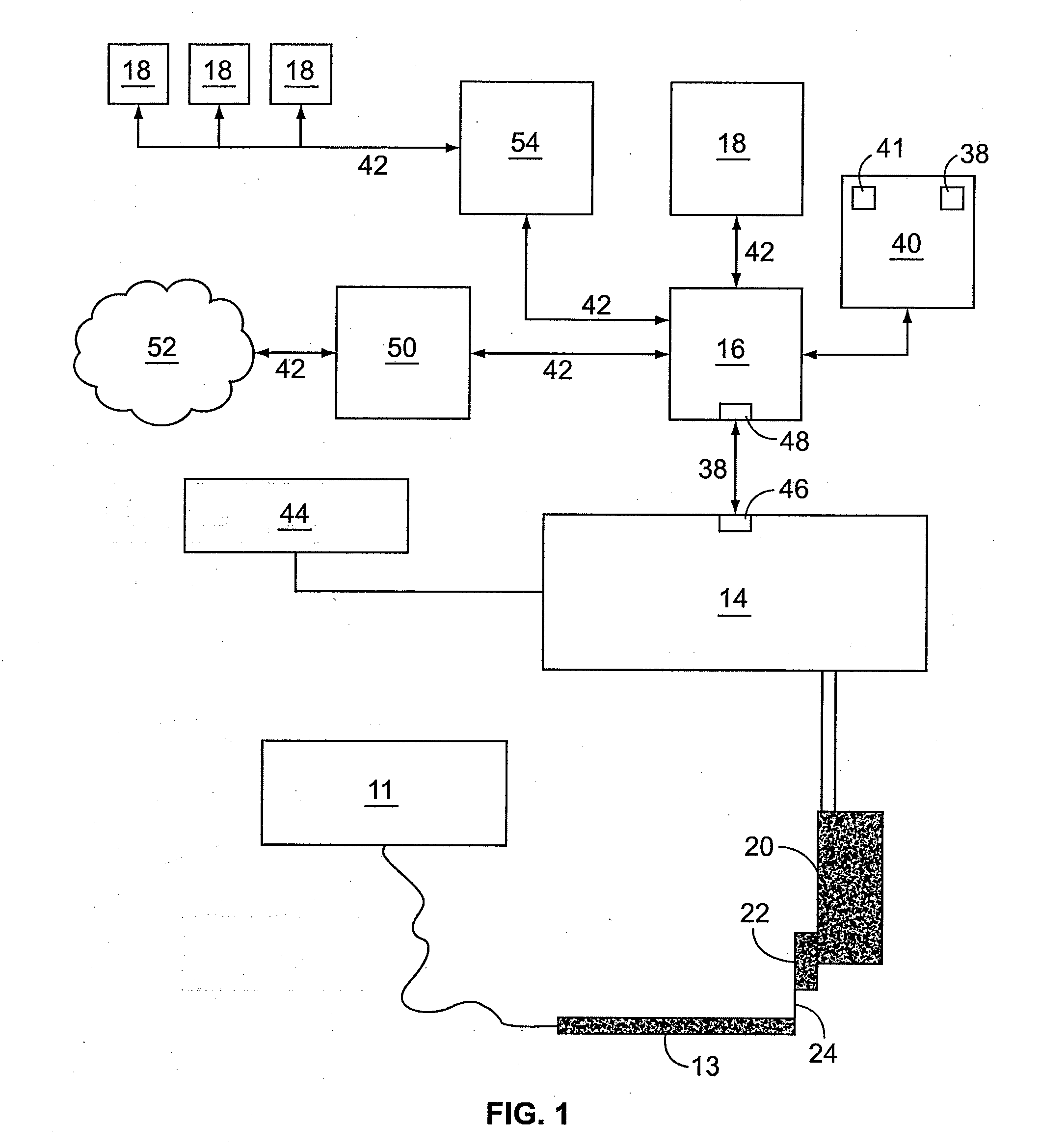
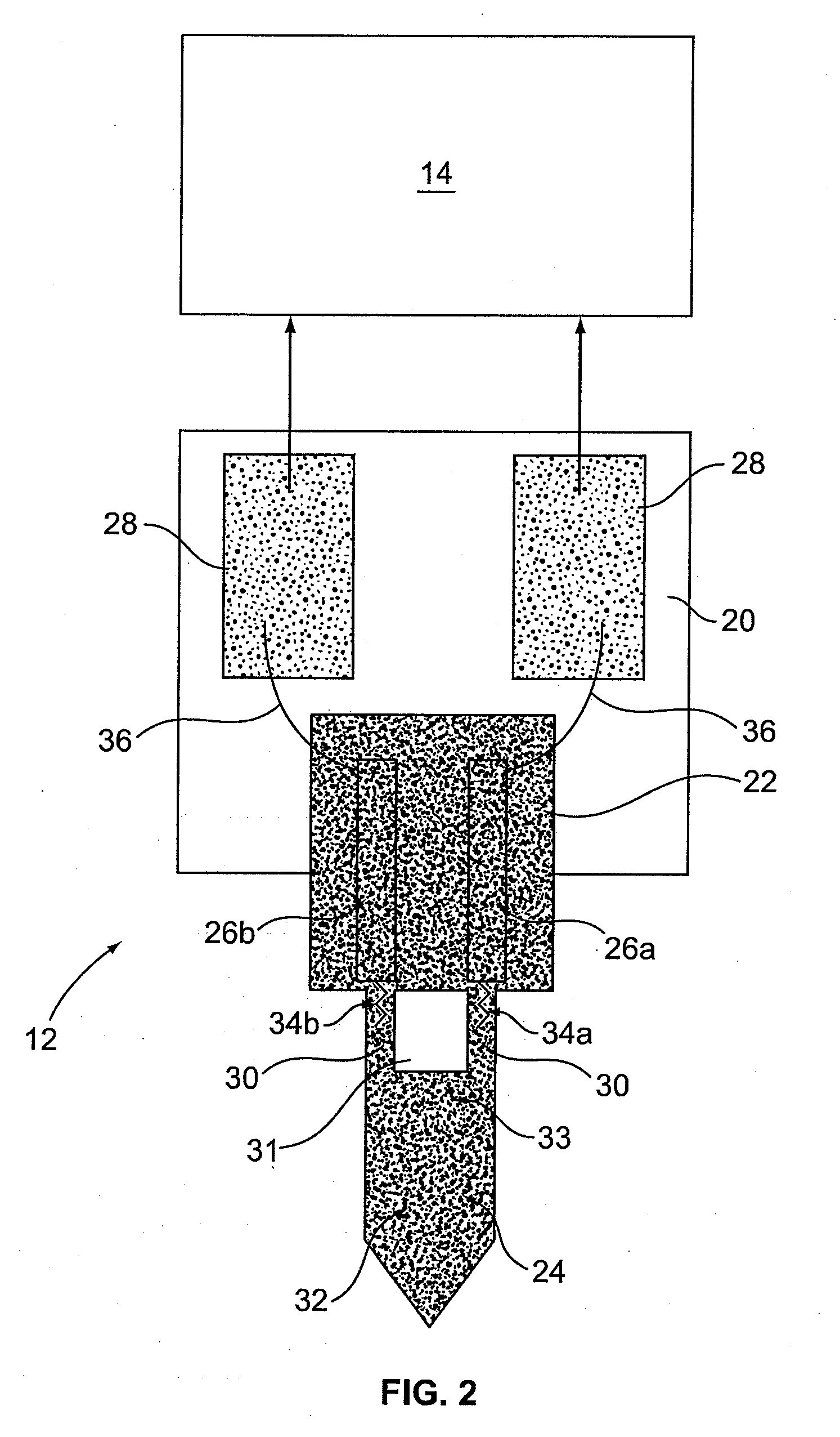
[0050]Referring to the figures, and initially to FIGS. 1 and 2, an apparatus 10 for measuring the viscosity of a fluid 11 is shown. The apparatus 10 generally includes a sensor 12, an electrical circuit amplification element 14, a processor 16 in communication with the electrical circuit amplification element 14, and a user interface device 18 in communication with the processor 16. A portion of the sensor 12 extends into a flow path 13 of the fluid 11 to sense one or more parameters of the fluid 11. It is understood that connections and communications between the components of the apparatus 10, including t...


PUM


Abstract

The disclosure presents an apparatus and method for measuring viscosity of a lubricating oil. The apparatus has a piezo-resistive cantilever sensor for sensing a first oil viscosity parameter. The sensor has a cantilever having a pressure receiving portion for receiving pressure exerted by the lubricating oil as the lubricating oil comes into contact with the pressure receiving portion. The cantilever also has first and second resistive portions in electrical communication with a first lead and a second lead, respectively, which are in electrical communication with an electrical circuit amplification element, for creating an output signal indicative of a change in the resistive characteristics of the first and second resistive portions of the cantilever as the lubricating oil comes into contact with the pressure receiving portion. The output signal can be used for determining oil viscosity. A processor and memory compare the output signal value with a stored resistance value to provide information relating to the quality of the lubricating oil.

Description

CROSS-REFERENCE TO RELATED APPLICATIONS[0001]This application claims priority from U.S. Patent Application Ser. No. 60 / 908,213 entitled “Petroleum Viscosity Measurement and Communication System and Method”, filed Mar. 27, 2007, which is incorporated herein by reference in its entirety.TECHNICAL FIELD[0002]The present invention is related to a system and method for measuring viscosity of a liquid, such as for example petroleum. More particularly, the present invention relates to a system and method for measuring attributes of petroleum, analyzing the attributes to determine petroleum viscosity, and communicating related information to target locations.BACKGROUND OF THE INVENTION[0003]Several prior systems and methods exist to measure and utilize viscosity measurements of motor oil an automobile and provide a driver with information on whether the motor oil should be changed. Specifically, U.S. Pat. No. 6,695,470 B1 to Berndorfer et al. is directed to an apparatus and method for deter...

Claims


Application Information

Patent Timeline
IPC IPC(8): G01N11/00G01N33/26G01N37/00
CPCG01N11/16G01N33/2888
Inventor QUIST, ARJANLAL, RATNESHLIESEN, GREGORY P.SRIVASTAVA, SUNIL K.
Owner RICHMOND CHEM CORP
Why Eureka
Try Eureka