Proximity detection system and method

a detection system and proximity technology, applied in the direction of signaling systems, pulse techniques, instruments, etc., can solve problems such as failure to detect touch, and achieve the effect of improving the proximity detection system and

Active Publication Date: 2008-11-27
ANALOG DEVICES INC
View PDF3 Cites 18 Cited by
  • Summary
  • Abstract
  • Description
  • Claims
  • Application Information

AI Technical Summary

Benefits of technology

[0004]It is therefore an object of this invention to...

Problems solved by technology

A problem with sensors such as proximity detectors is that once a spurious touch indication has occurred the system blocks out further valid touches until that spurious touch indication ends so subsequent touches are not detected, i.e. locked out.
Another problem with maintaining the proper background average in conventional approaches is that, if the background average increases above the present level or...

Method used


Image

  • Proximity detection system and method
  • Proximity detection system and method
  • Proximity detection system and method

Examples


Embodiment Construction

[0035]Aside from the preferred embodiment or embodiments disclosed below, this invention is capable of other embodiments and of being practiced or being carried out in various ways. Thus, it is to be understood that the invention is not limited in its application to the details of construction and the arrangements of components set forth in the following description or illustrated in the drawings. If only one embodiment is described herein, the claims hereof are not to be limited to that embodiment. Moreover, the claims hereof are not to be read restrictively unless there is clear and convincing evidence manifesting a certain exclusion, restriction, or disclaimer.

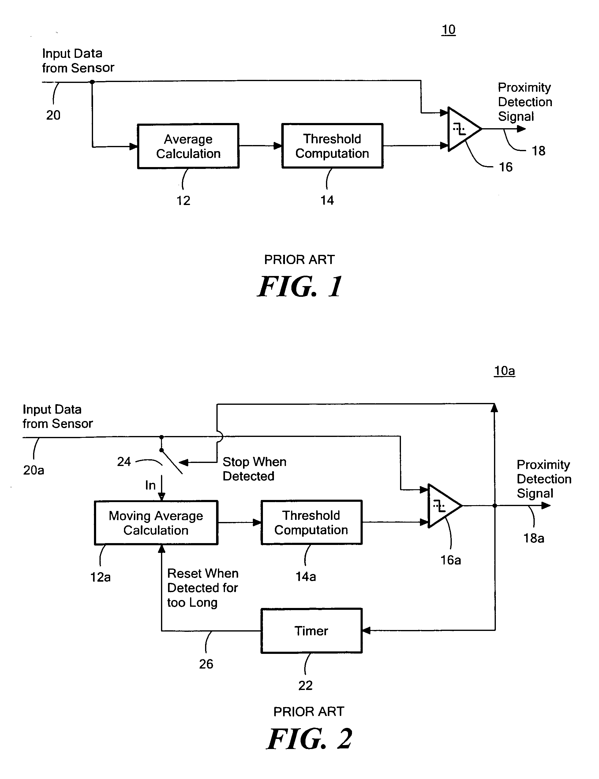
[0036]There is shown in FIG. 1 a prior art proximity detector 10 including an average calculation circuit 12, threshold computation circuit 14, and a comparator 16. In operation the input data is delivered directly to one input of comparator 16 and also to the average calculation circuit 12 which calculates the average over...


PUM


Abstract

Proximity detection is accomplished by determining with a moving average calculation a moving average level of input data; setting a threshold level in response to the average level and a sensitivity factor; producing a proximity detection output when the input data meets the threshold level; and changing the weighting used by the average level calculation in response to a proximity detection output.

Description

RELATED APPLICATIONS[0001]This application claims benefit of and priority to U.S. Provisional Application Ser. No. 60 / 931,446 filed May 23, 2007, incorporated herein by this reference.FIELD OF THE INVENTION[0002]This invention relates to a proximity detection system such as a rain or touch sensor and more particularly to improvements in generating and controlling background average levels for determining proximity detection.BACKGROUND OF THE INVENTION[0003]Conventional proximity detection, e.g. touch and rain sensors typically rely on a moving average to represent slowly varying environmental background conditions against which valid signals can be detected above a selected threshold. A problem with sensors such as proximity detectors is that once a spurious touch indication has occurred the system blocks out further valid touches until that spurious touch indication ends so subsequent touches are not detected, i.e. locked out. One solution to this has been to simply time-out the sy...

Claims


Application Information

Patent Timeline
IPC IPC(8): H03K17/945
CPCH03K17/945H03K2217/94026
Inventor O'DOWD, JOHNBRYCHTA, MICHAL
Owner ANALOG DEVICES INC
Why Eureka
Try Eureka