
Efficient rendering of panoramic images, and applications thereof

a panoramic image and efficient technology, applied in the field of rendering panoramic images, can solve the problems of unfavorable cpu consumption, and achieve the effects of simple computation and data copy, quick rendering, and convenient handling

Active Publication Date: 2008-11-27
GOOGLE LLC
View PDF8 Cites 111 Cited by
  • Summary
  • Abstract
  • Description
  • Claims
  • Application Information

AI Technical Summary

Benefits of technology

[0003]The present invention provides for efficient rendering of images such as panoramic images, and applications thereof. In an embodiment, a precomputation is made of (a) a region on a surface defined by a first transformation from a viewport to the surface and (b) a second transformation that maps from the precomputed region to the viewport. In order to render the surface on the viewport, the renderer determines what portion of the image intersects with the precomputed region and proceeds to apply the precomputed second transformation to the portion of the image, thereby resulting in a transformed image which can be rendered in the viewport for display. The transformations can be defined on corresponding meshes on the surface and viewport or can be made continuous (e.g., voxel-to-pixel). The embodiment is particularly advantageous where the surface is a cylinder. In the case of a cylinder, any change in orientation of the viewport with regard to the cylinder can be readily handled by merely translating the image in a corresponding direction resulting in a change in the intersection of the precomputed region and the image. Accordingly, for example, changes to a cylindrical panoramic image as a user changes a point of view can be quickly rendered using the precomputed transformation and simple computations and data copies.

Problems solved by technology

This unfortunately can be CPU intensive: the points on the mesh are typically updated (that is, rotated and shifted) while the visible portion of the cylinder is recomputed, and the texture mapping recomputed for each polygon of the mesh (because it is attached to the cylindrical mesh that was updated).

Method used


Image

  • Efficient rendering of panoramic images, and applications thereof
  • Efficient rendering of panoramic images, and applications thereof
  • Efficient rendering of panoramic images, and applications thereof

Examples


Embodiment Construction

[0022]The present invention provides for efficient rendering of panoramic images, and applications thereof. In the detailed description of the invention herein, references to “one embodiment”, “an embodiment”, “an example embodiment”, etc., indicate that the embodiment described may include a particular feature, structure, or characteristic, but every embodiment may not necessarily include the particular feature, structure, or characteristic. Moreover, such phrases are not necessarily referring to the same embodiment. Further, when a particular feature, structure, or characteristic is described in connection with an embodiment, it is submitted that it is within the knowledge of one skilled in the art to effect such feature, structure, or characteristic in connection with other embodiments whether or not explicitly described.

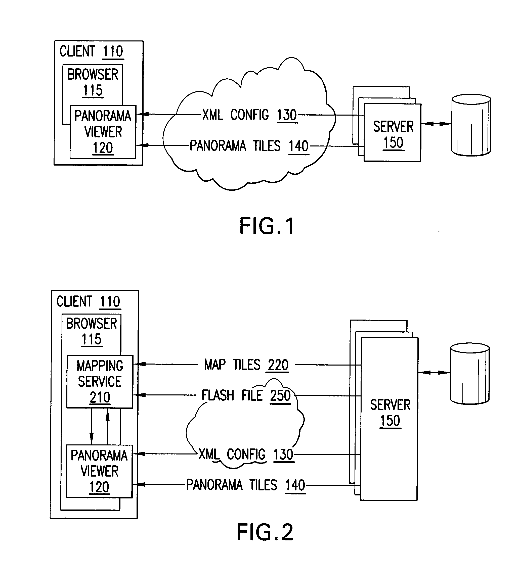
[0023]FIG. 1 is a distributed system suitable for practice of an embodiment of the invention. A client 110 communicates with one or more servers 150, for example...


PUM


Abstract

A fast renderer for panoramic images is herein disclosed. In an embodiment, a precomputation is made of (a) a region on a surface defined by a first transformation from a viewport to the surface and (b) a second transformation that maps from the precomputed region to the viewport. In order to render the surface on the viewport, the renderer determines what portion of the image intersects with the precomputed region and proceeds to apply the precomputed second transformation to the portion of the image, thereby resulting in a transformed image which can be rendered in the viewport for display.

Description

FIELD OF THE INVENTION[0001]The present invention generally relates to displaying imagery, and more particularly to rendering of panoramic images, and applications thereof.BACKGROUND[0002]Computerized methods for displaying imagery are known. Existing viewers for panoramic images such as Apple Quicktime VR support rendered surfaces such as cylindrical projections. Nevertheless, most such tools are based on the idea of mapping the imagery as a texture attached to a discretized cylinder / mesh. When the user changes the point of view, the cylinder is shifted / rotated accordingly. This unfortunately can be CPU intensive: the points on the mesh are typically updated (that is, rotated and shifted) while the visible portion of the cylinder is recomputed, and the texture mapping recomputed for each polygon of the mesh (because it is attached to the cylindrical mesh that was updated). There is a need for faster techniques for rendering such images, in particular for slower browser-based Intern...

Claims


Application Information

Patent Timeline
IPC IPC(8): G06T15/20
CPCG06T15/205
Inventor LAFON, STEPHANE
Owner GOOGLE LLC
Learn More