
Position and orientation measurement apparatus and control method thereof

a technology of positioning and orientation measurement and measurement apparatus, which is applied in the direction of instruments, image analysis, image enhancement, etc., can solve the problems of difficult to attach giant indices onto the wall surface of measurement objects, preparation processes are required, and the indices used to detect the position and orientation cannot always be attached to measurement objects, so as to maintain the consistency of data sets and simplify procedures

Inactive Publication Date: 2008-11-27
CANON KK
View PDF3 Cites 31 Cited by
  • Summary
  • Abstract
  • Description
  • Claims
  • Application Information

AI Technical Summary

Benefits of technology

[0033]The present invention has been made in consideration of the aforementioned problems, and provides a position and orientation measurement apparatus which can maintain consistency of data sets even when a 3D model of a measurement object has been geometrically changed, according to its exemplary embodiment. Also, the present invention provides a position and orientation measurement apparatus which can simplify procedures required to estimate the position and orientation of a measurement object having a complicated shape.

Problems solved by technology

However, upon assuming the use over a broad range, the indices used to detect the position and orientation cannot always be attached to a measurement object.
For example, when a measurement object is an architectural structure such as a building or the like, it is difficult to attach giant indices onto its wall surface.
However, even in this case, since it is required to exhaustively calculate possible positions and orientations, preparation processes are required.
For this reason, huge amounts of time are required with increasing number of reference images.
For this reason, it is difficult to apply the method that calculates the image correlations between the edges of many reference images and those of a captured image like in reference 1.
As another problem, when a measurement object is configured by a plurality of structural objects, and some of these structural objects are free to move, since the motion of each movable object is unknown, reference images cannot be acquired in advance.
Since this method does not require any correlation calculations between the reference images and a captured image, the processing time is short.
However, an actual captured image includes many noise components.
Factors that influence the estimation precision include erroneous detection and non-detection of edges.
A line segment which is not observed on a captured image is selected as a measurement object unless it is checked whether or not that line segment is hidden by another plane, and the position and orientation estimation precision cannot be improved.
However, since other edges are erroneously detected as corresponding edges, such line segments are handled as points having large errors.
However, in this case, since the measurement object needs to be a 3D model such as a simple rectangular parallelepiped or rectangle, such object has a narrow application range to an actual scene.
In general, upon handling a measurement object having a complicated shape, it is difficult to set information of the configuration and that of the measurement line segments to be the same.
However, such polygons have a problem in the use as measurement line segments.
Therefore, the configuration planes of a 3D model cannot be used as information of measurement line segments for registration intact.
However, such configuration suffers the following problem.
For example, it is difficult to maintain consistency between information of the configuration planes of the measurement object, and actual measurement line segments, and a flexible change of the measurement object cannot be coped with.
Since there are no procedures using the aforementioned method of estimation of position and orientation while maintaining consistency between data sets of the configuration planes of objects used there and those used in measurement, such position and orientation estimation apparatus has poor convenience.

Method used


Image

  • Position and orientation measurement apparatus and control method thereof
  • Position and orientation measurement apparatus and control method thereof
  • Position and orientation measurement apparatus and control method thereof

Examples


Embodiment Construction

[0067]Exemplary embodiments of the present invention will now be described in detail in accordance with the accompanying drawings.

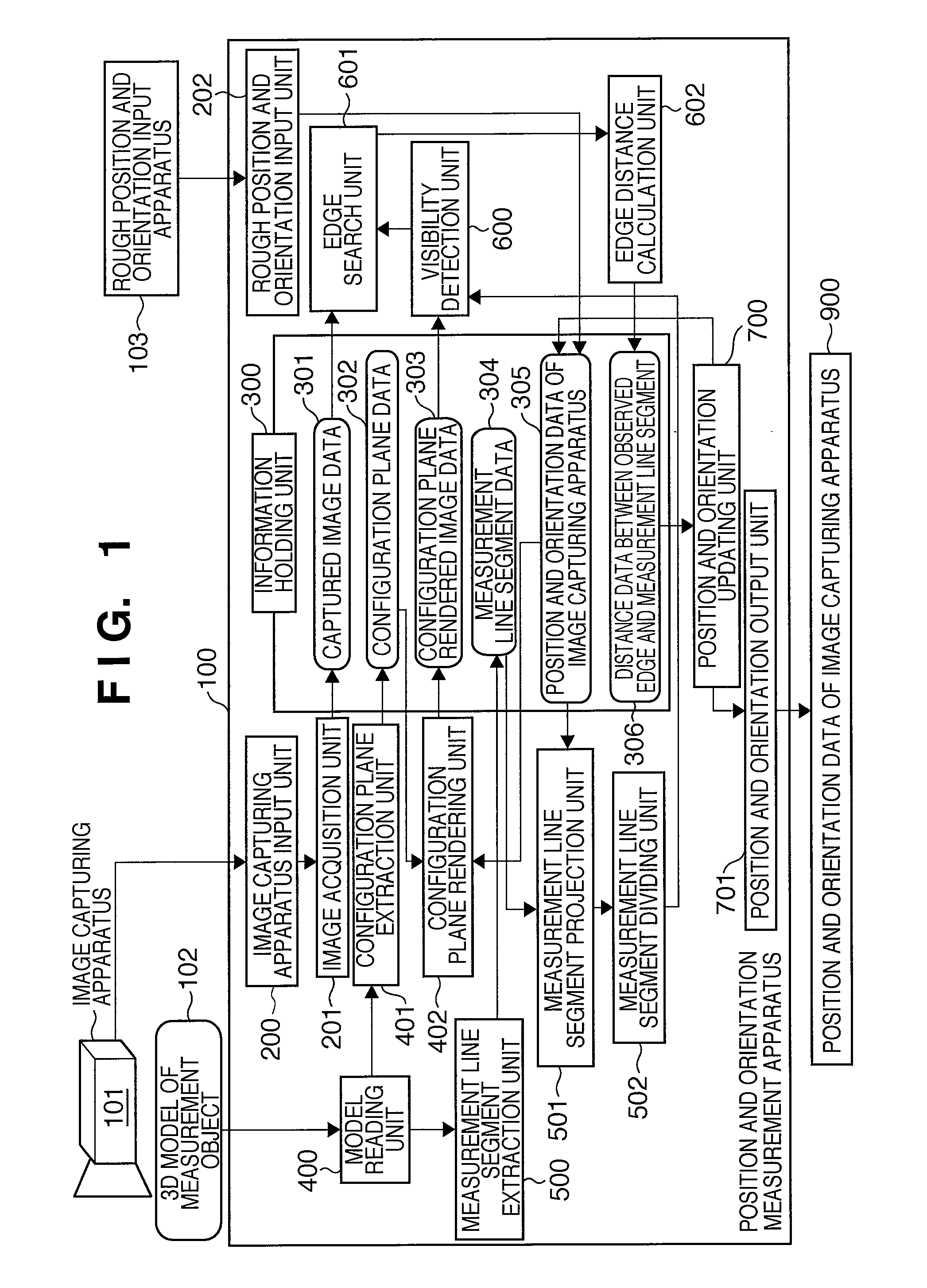
[0068]FIG. 1 is a block diagram showing the arrangement when a position and orientation measurement apparatus 100 according to an embodiment of the present invention is applied to an image capturing apparatus 101. Note that the position and orientation measurement apparatus 100 comprises processors for executing respective processes, and a holding unit for holding information. The position and orientation measurement apparatus 100 may be a dedicated apparatus, or it can be implemented when an application program used to execute control of position and orientation measurement to be described later is executed in a general-purpose computer. In this case, an information holding unit 300 shown in FIG. 1 comprises a hard disk, RAM, or the like, and other units are implemented when the computer executes the application program. Such configuration is apparent to...


PUM


Abstract

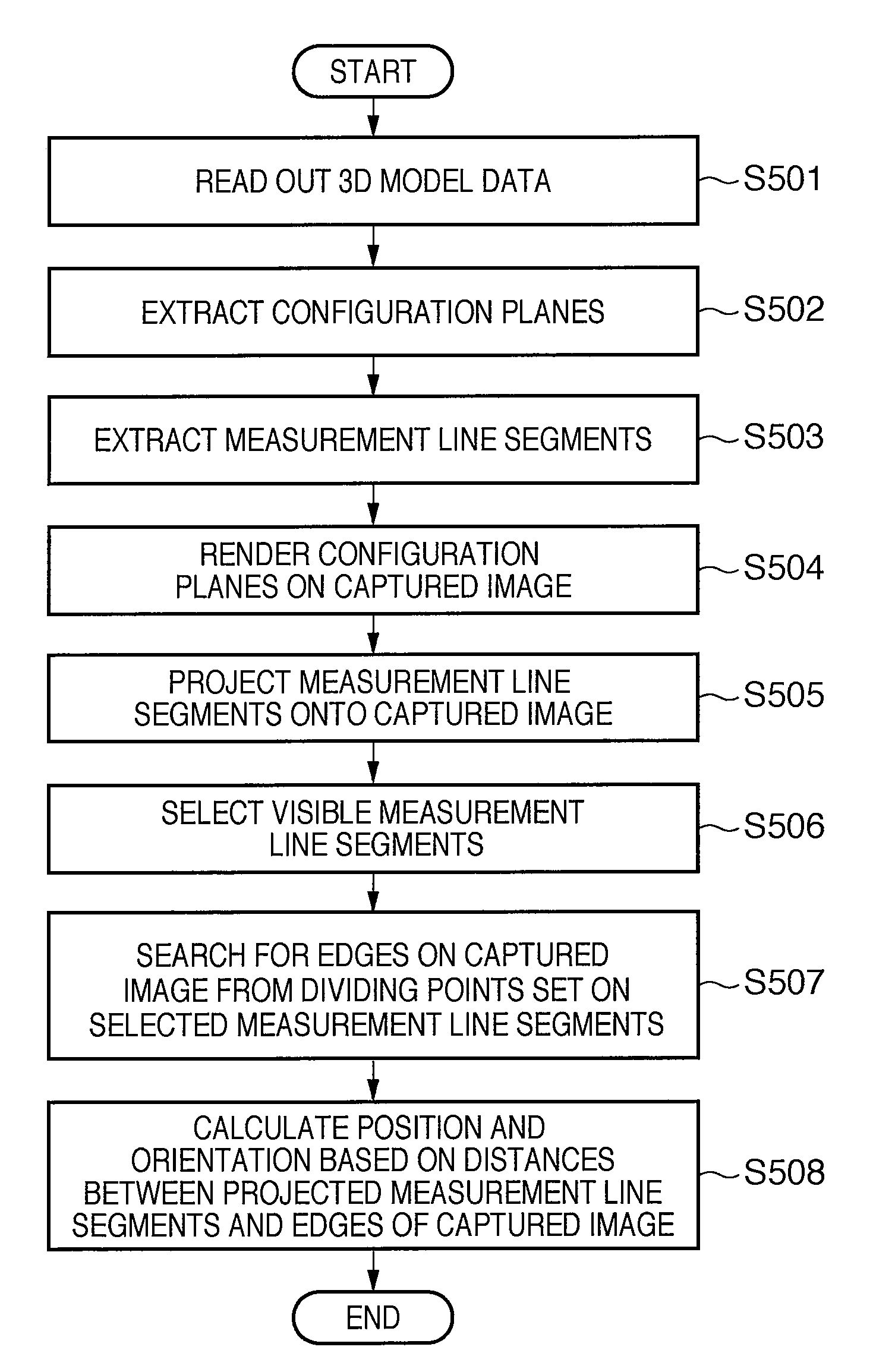
A position and orientation measurement apparatus for measuring the position and orientation of an image capturing apparatus, which captures an image of a measurement object, relative to the measurement object, extracts configuration planes of the measurement object based on three-dimensional model data of the measurement object, and extracts measurement line segments to be used in detection of edges of a captured image from line segments which form the configuration planes. The position and orientation measurement apparatus projects the extracted measurement line segments onto the captured image based on an estimated position and orientation of the image capturing apparatus, selects visible measurement line segments which are not hidden by the extracted configuration planes, and calculates the position and orientation of the image capturing apparatus relative to the measurement object based on the visible measurement line segments and corresponding edges of the captured image.

Description

BACKGROUND OF THE INVENTION[0001]1. Field of the Invention[0002]The present invention relates to a position and orientation measurement technique for measuring the position and orientation of an image capturing apparatus based on the distance between a position where a model of a measurement object is projected onto a captured image, and the position of the measurement object observed from the captured image.[0003]2. Description of the Related Art[0004]The position and orientation measurement of an image capturing apparatus (to be also referred to as “camera” hereinafter as needed) such as a camera that captures an image of a physical space and the like is required in, for example, a mixed reality system which blends and displays the physical space and a virtual space.[0005]In general, as a method of measuring the position and orientation of an image capturing apparatus, a method of attaching indices, whose three-dimensional (3D) positions are given, to a measurement object is discl...

Claims


Application Information

Patent Timeline
IPC IPC(8): G06K9/46G06V10/147G06V10/24
CPCG06K9/209G06K9/32G06T7/0046G06T7/0083G06T2207/30244G06T7/75G06T7/12G06V10/147G06V10/24
Inventor KOBAYASHI, KAZUHIKOUCHIYAMA, SHINJI
Owner CANON KK
Learn More