Raceway IDC Connector

Inactive Publication Date: 2008-11-27
PANDUIT
View PDF34 Cites 6 Cited by
  • Summary
  • Abstract
  • Description
  • Claims
  • Application Information

AI Technical Summary

Benefits of technology

[0008]Terminating the electrical component wiring to the IDC connector in the factory or at a time before field installation of the electrical component may reduce the time and labor necessary to install and terminate IDC connectors. Because the factory wiring may be already installed in a first side of the IDC connector, the field technician may only need to install the field wiring in a second side of the IDC connector.
[0009]The IDC connector may be easily mounted to existing raceways, outlet strips, and junction boxes. This may increase efficiency, as less time is required to install the connectors after the wiring has been terminated.

Problems solved by technology

One problem that exists when terminating wires using an IDC connector is that a great deal of force may be required for the field technician to properly push down the cover onto the connector and thereby terminate the connections.
However, the force required to pierce the wire insulation may be large, so that it is uncomfortable or inconvenient for the field technician to terminate the contacts.
An additional problem is that, typically, the field technician must install a connector on each side that is to be terminated.
This takes time and, as previously stated, may require a great deal of physical effort on the part of the technician to properly terminate the wires.
Another problem is that alter terminating the IDC, it may be desirable to place the connector in a field configuration, i.e., on a raceway, in an electrical box, in an outlet strip, or another configuration.
Connectors that are not adapted to be easily installed in such field configurations may require extra time from the field technician to complete the installation.

Method used


Image

  • Raceway IDC Connector
  • Raceway IDC Connector
  • Raceway IDC Connector

Examples


Embodiment Construction

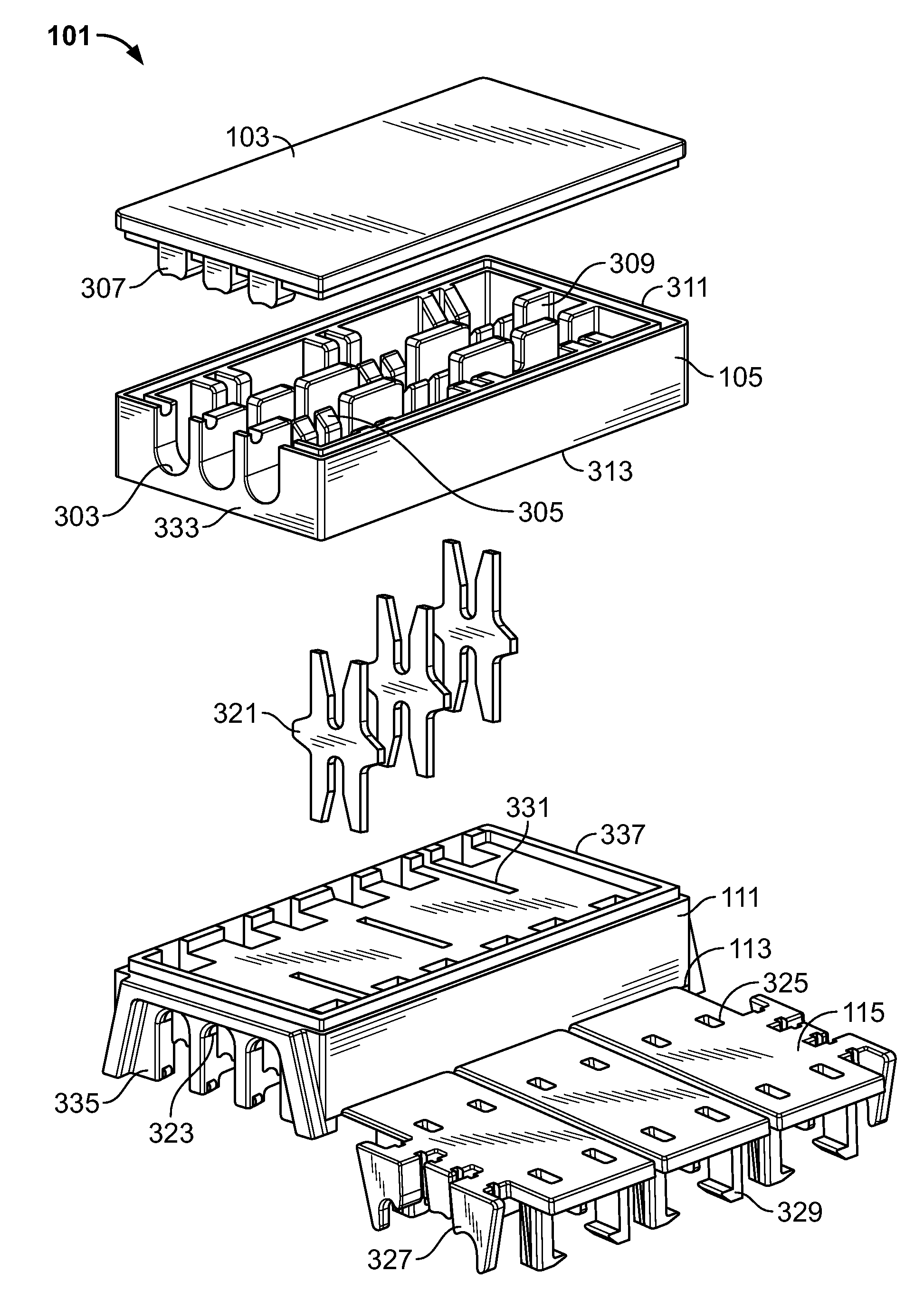
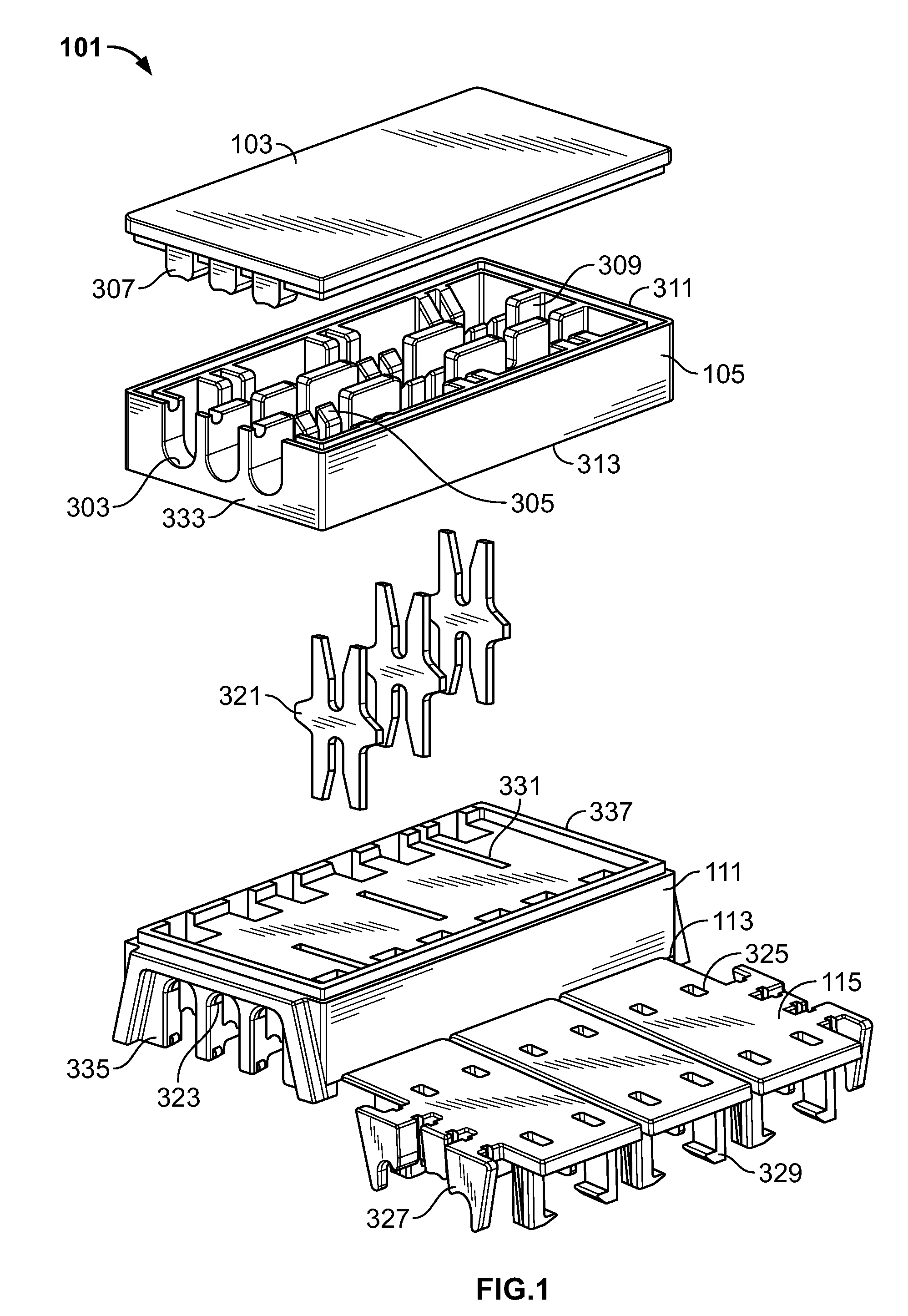
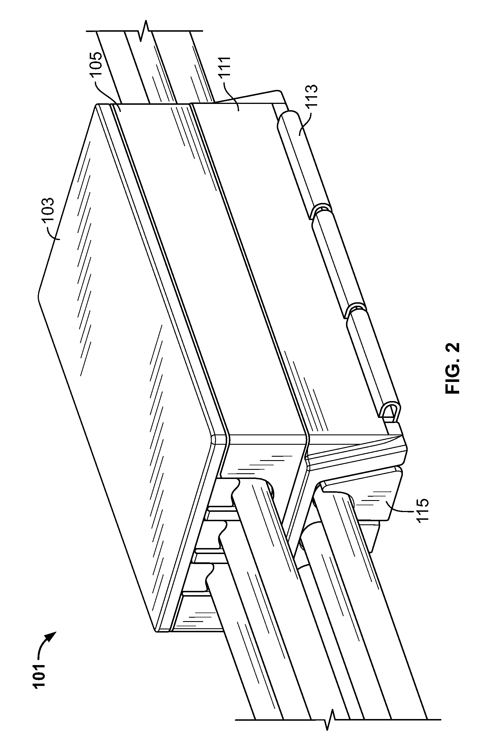
[0028]FIG. 1 is a front upper right expanded view of an insulation displacement contact (“IDC”) connector 101. The IDC connector 101 has a factory housing 105, a factory cover 103, a field housing 111, field covers 115, and IDC's 321.

[0029]The factory housing 105 may have two side walls, a front wall 333, and an end wall 311. One or more factory wire apertures 303 may be located on the front wall 333 and the end wall 311 of the factory housing 105.

[0030]The factory housing 105 is shown in FIGS. 1-13d as having factory wire apertures 303 only on the front wall 333. Frequently, wires from electrical components may be installed into an IDC connector in an end-wiring configuration. In this case, it may be desirable to have a solid end wall 311, as shown in FIGS. 1-13d.

[0031]Alternatively, factory wire apertures 303 may be located on the end wall as shown with respect to the front wall 333. Wiring from the electrical component may be installed in a through-wiring configuration, and the ...


PUM

PropertyMeasurementUnit
Pressureaaaaaaaaaa
Sizeaaaaaaaaaa
Flexibilityaaaaaaaaaa

Abstract

A dual-sided IDC connector for use in connecting electrical components to field wiring is described. One side of the IDC connector may be factory-wired to an electrical component. A second side of the IDC connector may be field-wired in an end-wiring or a through-wiring configuration. The second side of the IDC connector may have multiple covers to minimize the effort required by a field technician to terminate the field-wiring. The IDC connector may be easily mounted to existing raceways, outlet strips, and junction boxes.

Description

CROSS REFERENCE TO RELATED APPLICATION [0001]This application claims priority from U.S. Provisional Patent Application No. 60 / 939,425, filed May 22, 2007, the entire disclosure of which is hereby incorporated by reference.FIELD OF THE INVENTION [0002]The present invention relates generally to electrical connectors and, more particularly, to a dual-sided insulation displacement contact (“IDC”) connector for use in field-wiring and factory-wiring, capable of being installed in a raceway, outlet strip, and other electrical field installations.BACKGROUND OF THE INVENTION [0003]Electrical connectors are used to connect many types of insulated wires, and enable technicians to connect insulated wires without having to strip and crimp the wires. Typically, an IDC connector may be a housing with channels for wires to pass through, a cover, and one or more IDC's. IDC's comprise an electrically conductive material, and may have a “U” shape on one or more sides. IDC's may pierce through the wir...

Claims


Application Information

Patent Timeline
IPC IPC(8): H01R11/20H01R43/00
CPCH01R4/2433H01R9/031H01R13/502Y10T29/49169H01R13/506H01R13/508H01R25/142H01R13/504
Inventor CAVENEY, JACK E.BROUWER, SHAUN P.BLOCK, DALE A.
Owner PANDUIT
Why Eureka
Try Eureka