Ultrasonic Imaging Apparatus

a technology of ultrasonic imaging and equipment, applied in the field of ultrasonic imaging equipment, can solve the problems of inability to reduce the transmission circuit or transmission/reception circuit, the circuit size to be enlarged,

Inactive Publication Date: 2008-11-27
HITACHI MEDICAL CORP
View PDF7 Cites 56 Cited by
  • Summary
  • Abstract
  • Description
  • Claims
  • Application Information

AI Technical Summary

Benefits of technology

[0013]Here, the transmission means will be described. The transmission means transmits ultrasonic waves from the respective transducers by inputting a common drive signal by the group. Also the transmission means selects all groups or predetermined groups out of the plurality of groups, supplying driving signals to the transducers belonging

Problems solved by technology

However, transmission means and reception means cause circuit size to be enlarged since each transducer needs a circuit.
However, a configuration of the trans

Method used


Image

  • Ultrasonic Imaging Apparatus
  • Ultrasonic Imaging Apparatus
  • Ultrasonic Imaging Apparatus

Examples


Embodiment Construction

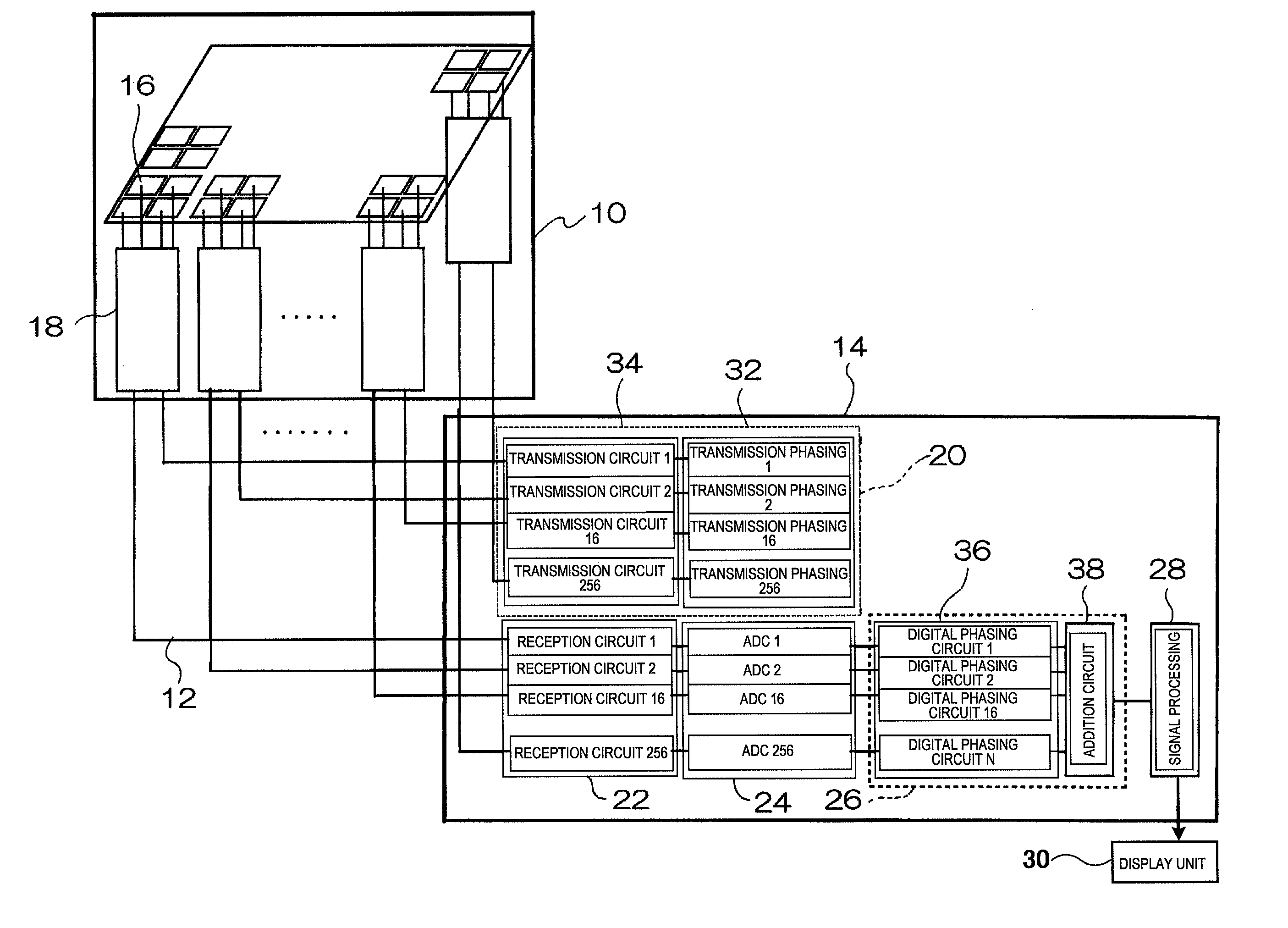
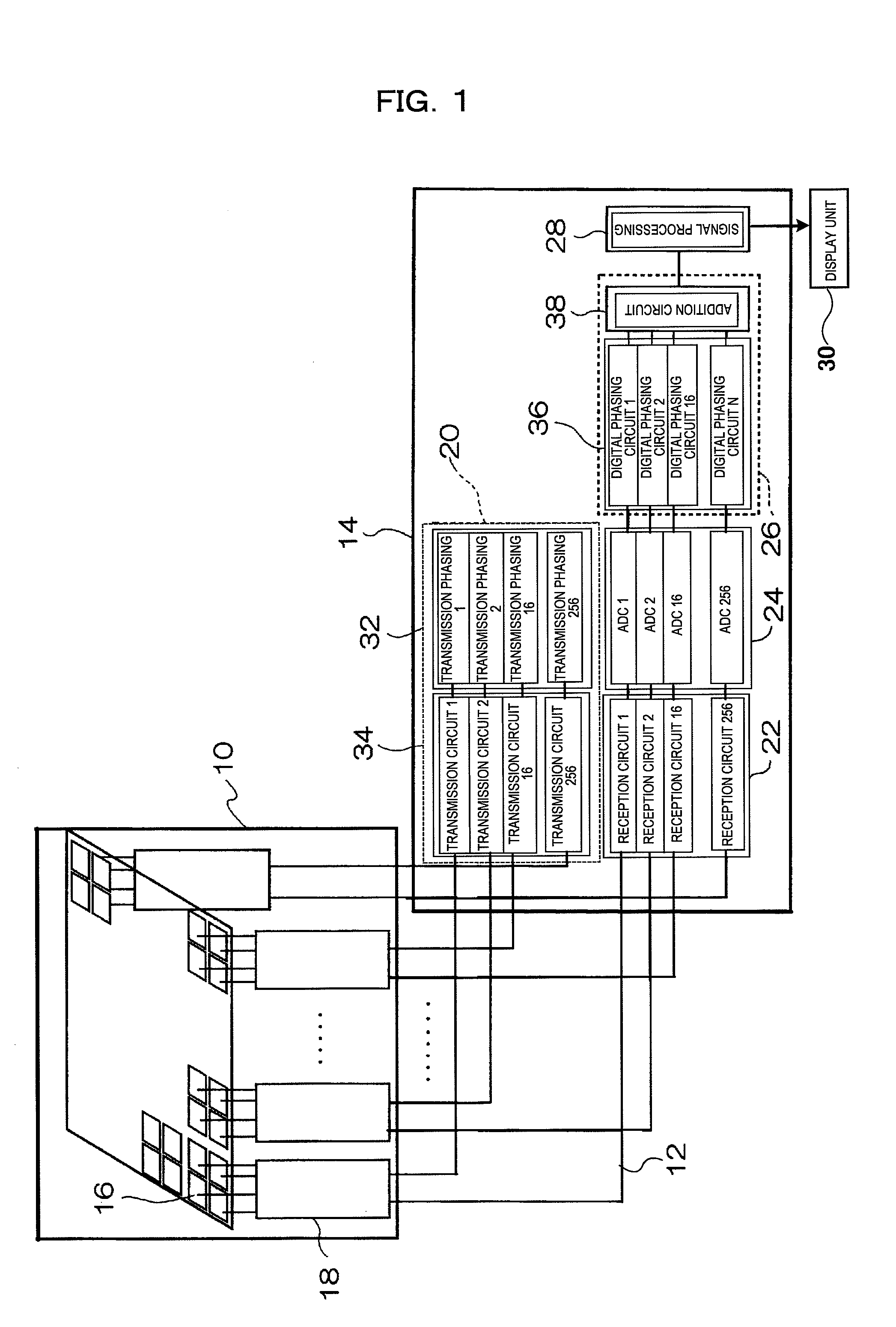
[0027]One embodiment of the ultrasonic imaging apparatus to which the present invention is applied will be described referring to FIGS. 1 ˜4. FIG. 1 is a block diagram of the ultrasonic imaging apparatus to which the present invention is applied. As shown in FIG. 1, the ultrasonic imaging apparatus is configured by ultrasound probe 10 being connected to main unit 14 via a plurality of cables 12.

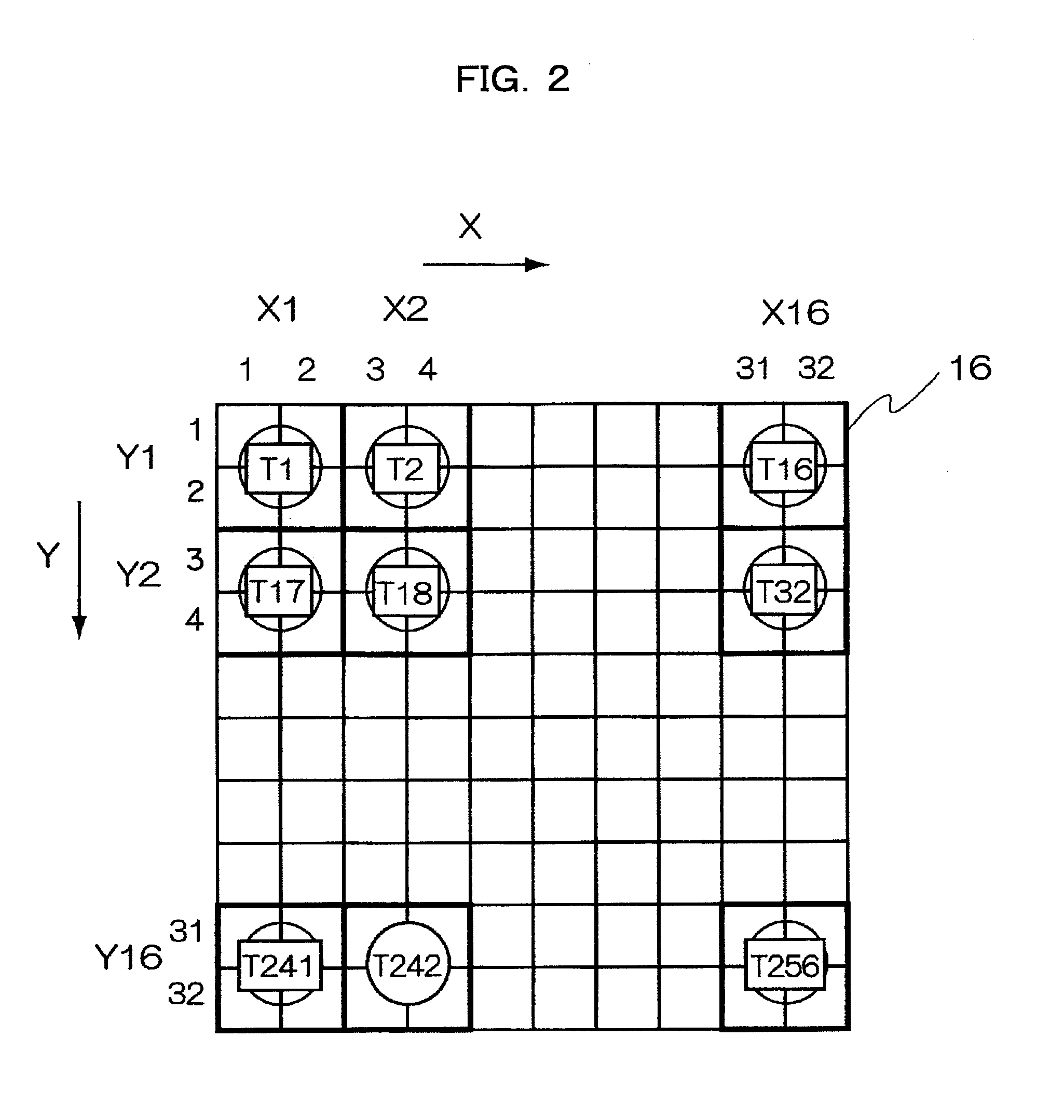
[0028]Ultrasound probe 10 is constructed by 2-dimensionally arraying a plurality of (for example, 1024) transducers 16 for transmitting and receiving ultrasonic beams to / from an object to be examined, and a plurality of transducers 16 is divided into a plural number-n (for example, 256) of groups. Also, n-units of bundle units 18 for supplying a common drive signal to transducers 16 belonging to the same group and performing the first phasing addition by the groups relating to the reflected echo signals outputted from transducers 16 is installed in the chassis of ultrasound probe 10. Each bun...


PUM


Abstract

It is possible to realize an ultrasonic imaging apparatus capable of eliminating deterioration of the S/N of the ultrasonic image while suppressing enlargement of the circuit size. The ultrasonic imaging apparatus includes: an ultrasonic probe having a plurality of transducers arranged for transmitting and receiving ultrasonic waves to/from an object to be examined; transmission means for supplying a drive signal to each of the transducers; reception means for phasing/adding and receiving a reflected echo signal received by each transducer; and an image processing unit for reconfiguring an ultrasonic image based on the reflected echo signal received. The transmission means divides the plurality of transducers into a plurality of groups, supplies a common drive signal to the transducers belonging to the same group, and performs focus control by group units.

Description

TECHNICAL FIELD[0001]The present invention relates to an ultrasonic imaging apparatus and a technique suitable for transmitting / receiving ultrasonic waves to / from an ultrasonic probe in which a plurality of transducers is arrayed.BACKGROUND ART[0002]An ultrasonic imaging apparatus radiates ultrasonic waves to an object to be examined from a plurality of transducers arrayed in an ultrasound probe, and constructs an ultrasonic image based on the reflected echo signals generated from the object. In this ultrasonic imaging apparatus, transmission means for performing focus control by providing predetermined delays to drive signals for being provided to the respective transducers of a probe and reception means for receiving the reflected echo signals being outputted from the respective transducers and performing phasing addition are provided. However, transmission means and reception means cause circuit size to be enlarged since each transducer needs a circuit.[0003]In a wave-receiving p...

Claims


Application Information

Patent Timeline
IPC IPC(8): A61B8/00
CPCA61B8/00G01S7/5208G01S7/52095G01S15/8925G01S15/8927G10K11/341G01S15/8915
Inventor SHINOMURA, RYUICHIASAFUSA, KALSUNORIOSHIKI, MITSUHIRO
Owner HITACHI MEDICAL CORP
Why Eureka
Try Eureka