Method for analyzing fluid flow within a three-dimensional object

a three-dimensional object and fluid flow technology, applied in the field of three-dimensional object analysis, can solve the problems of high level of skill and judgment, laborious and error-prone task, complex task that can only realistically be performed using computer models

Inactive Publication Date: 2008-11-27
VERO INT SOFTWARE UK +1
View PDF7 Cites 10 Cited by
  • Summary
  • Abstract
  • Description
  • Claims
  • Application Information

AI Technical Summary

Benefits of technology

[0052]It is still another object of the present invention to provide such an automated flow analysis system that uses prismatic solid mesh generation to give the user the ability to view cross sections of the models after the analysis stage.

Problems solved by technology

Flow analysis is a complex task that demands high levels of skill and judgment from those who use it, and is a task that can only realistically be performed using computer models.
As a moulded part typically consists of hundreds or thousands of faces this is a laborious and error prone task.
As a moulded part typically consists of hundreds of surfaces the generation of the mid-plane surfaces requires a lot of manual work and the process becomes a laborious manual and error prone task.
In this case the generation of the solid mesh is automatic, but the volume of data is immense.
The computation time for the flow analysis is very long, and in the majority of cases unacceptable in an industrial environment.
As will be appreciated, none of these prior patents even address the problem faced by applicant let alone offer the solutions proposed herein.

Method used


Image

  • Method for analyzing fluid flow within a three-dimensional object
  • Method for analyzing fluid flow within a three-dimensional object
  • Method for analyzing fluid flow within a three-dimensional object

Examples


Embodiment Construction

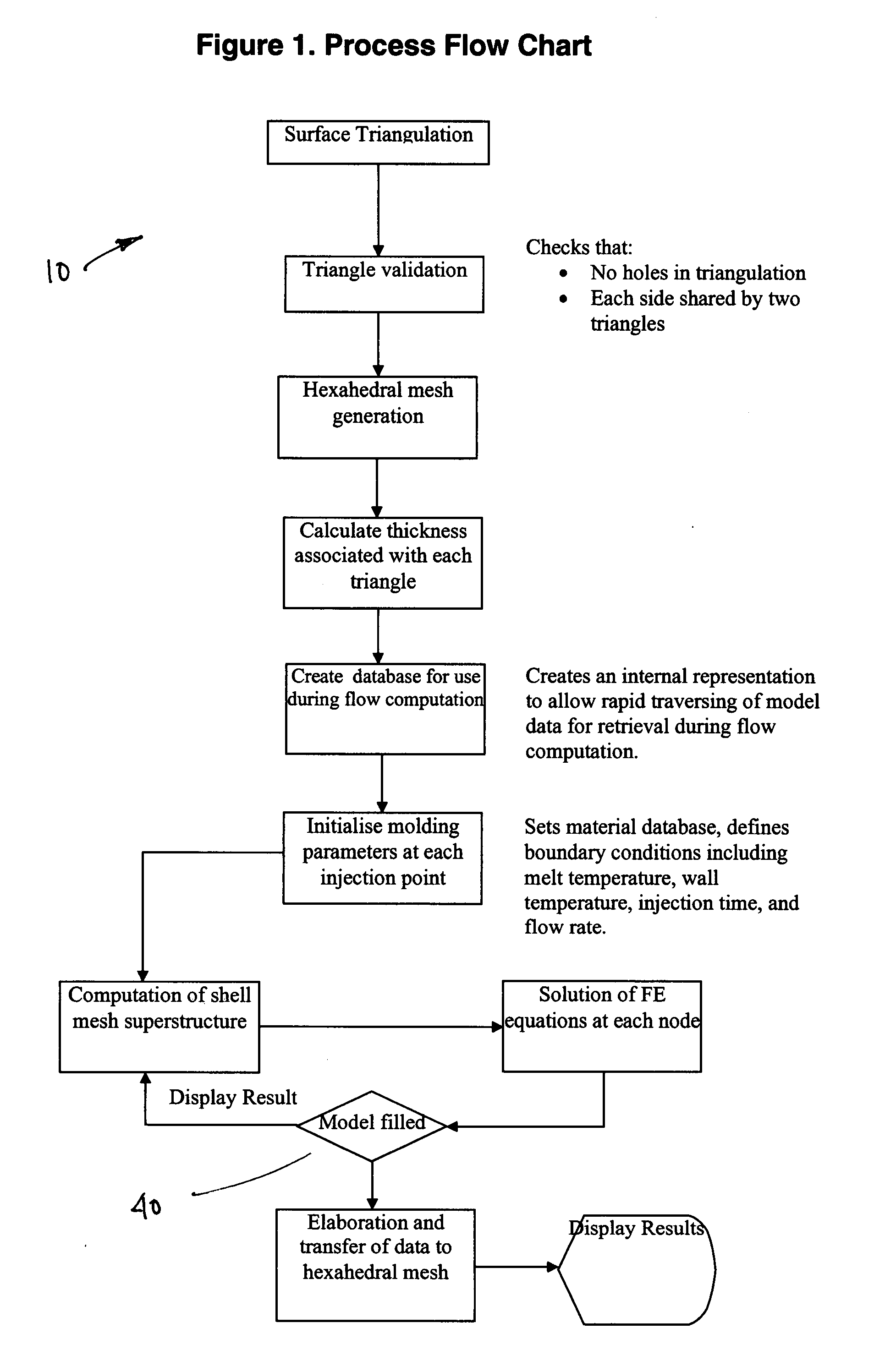
[0058]Referring to the drawings and, in particular, to FIG. 1 thereof, the flow analysis system of the present invention is provided and is referred to generally by reference numeral 10. The system 10 combines aspects of the mid-plane generation and prismatic filling systems in a way that is transparent to the user.

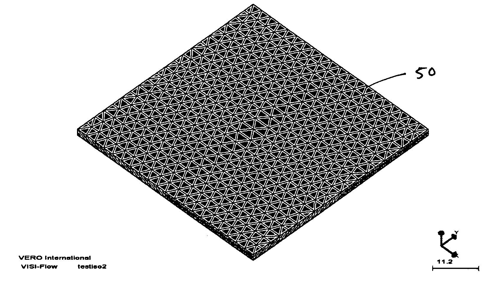
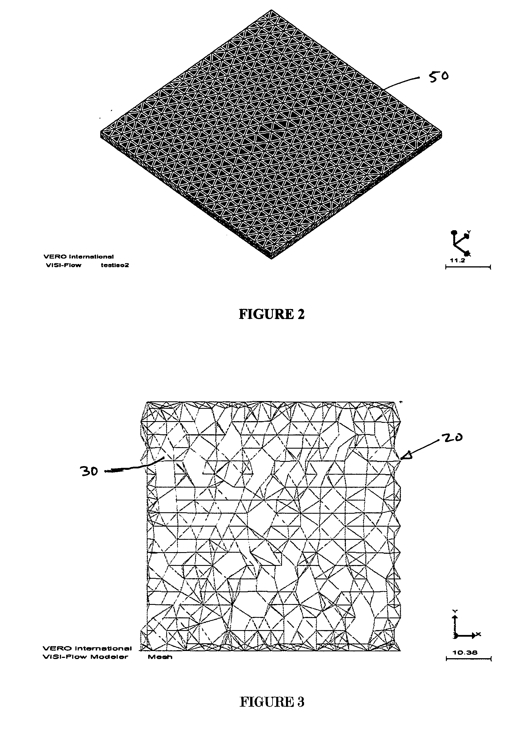
[0059]The system 10 of the present invention calculates the mid-plane mesh or shell mesh of a three-dimensional object in two stages. The first stage is to triangulate the faces of the solid model. FIG. 3 illustrates such a triangulated structure 20. It should be noted that the triangles 30 are very varied in size and shape. Some will be isosceles, some equilateral, and others will be long and thin. The triangle shapes depends upon the geometry of the part, and each triangle has an associated thickness.

[0060]The system 10 uses this triangulated structure to construct a solid mesh 40 that is used when the analysis is complete to provide feedback on the flow at cross sectio...


PUM


Abstract

A flow analysis system is provided comprising a fully automatic and dynamic system for performing flow analysis on solid models. The system combines aspects of the mid-plane generation and prismatic filling systems in a way that is transparent to the user. The generation of a mid-plane mesh and the flow analysis of the mesh proceed in parallel. The analysis can be halted at any stage, at which point the user can visualize the results of the partial analysis. The data on which the analysis is being performed, the mid-plane mesh, is totally invisible to the user. This system also uses prismatic solid mesh generation to give the user the ability to view cross sections of the models after the analysis stage.

Description

CROSS REFERENCES TO RELATED APPLICATIONS[0001]Not ApplicableSTATEMENT REGARDING FEDERALLY SPONSORED RESEARCH[0002]Not ApplicableREFERENCE TO APPENDIX[0003]Not ApplicableBACKGROUND OF THE INVENTION[0004]A. Field of the Invention[0005]The present invention relates to a method for analyzing fluid flow within a three-dimensional object, and more particularly to an automated flow analysis system, and, even more particularly, to a mid-plane flow analysis system wherein the generation of the mid-plane mesh and the analysis of the mid-plane mesh are synchronous dynamic operations.[0006]Injection molding is one of the most productive industrial processes used to produce plastic objects.[0007]Its advantage over other manufacturing process include the ability to produce both large and small complex parts, with aesthetic contours and restrictive tolerances. It enables high volume production without the need for secondary finishing operations using highly automated techniques.The process is base...

Claims


Application Information

Patent Timeline
Patent Type & Authority Applications(United States)
IPC IPC(8): G06G7/50
CPCG06F17/5018G06F2217/16G06F30/23G06F2111/10
Inventor MORONI, ANTONINO
Owner VERO INT SOFTWARE UK
Why Eureka
Try Eureka