Control Unit for Refrigerator and Method Controlling the Same

a technology for controlling units and refrigerators, applied in the field of refrigerators, can solve the problems of inability to display menus in different ways, inability to customize menus according to user requests, etc., and achieve the effect of simplifying the configuration of the input unit and being convenient to us

Active Publication Date: 2008-11-27
LG ELECTRONICS INC
View PDF12 Cites 74 Cited by
  • Summary
  • Abstract
  • Description
  • Claims
  • Application Information

AI Technical Summary

Benefits of technology

[0046]With the control unit for a refrigerator and a method of controlling the same according to the present invention, there are advantages in that more various menus can be displayed in different manners, and the configuration of the input unit is simplified so that the input unit can be more conveniently used.

Problems solved by technology

However, the conventional control unites for refrigerators have the following problems.
Accordingly, there are disadvantages in that menus of a variety of functions according to user's requests cannot be displayed and the menus cannot be displayed in different manners.

Method used


Image

  • Control Unit for Refrigerator and Method Controlling the Same
  • Control Unit for Refrigerator and Method Controlling the Same
  • Control Unit for Refrigerator and Method Controlling the Same

Examples


second embodiment

[0103]Next, the menu setting process and the detail setting process in the present invention will be described in greater detail with reference to the accompanying drawings.

[0104]FIG. 9 is a flowchart illustrating the menu setting and detail setting processes in the second embodiment of the present invention.

[0105]As shown in the figure, the main screen including the background screen 211 and the first and second information screens 212 and 213 is displayed on the display unit 210 in an initial state (S11). In this state, the microcomputer 250 determines whether the menu setting button 223 receives an operation signal, i.e., whether a user manipulates the menu setting button 223 (S12). Then, if it is determined that the menu setting button 223 is manipulated in step S12, the microcomputer 250 performs control such that the menu setting screen stored in the storage unit 230 is displayed on the display unit 210 (S13). At this time, the microcomputer 250 performs control such that the ...

third embodiment

[0124]Next, a control unit for a refrigerator according to the present invention will be described in greater detail with reference to the accompanying drawings.

[0125]FIG. 14 is a front view schematically showing a control unit for a refrigerator according to a third embodiment of the present invention.

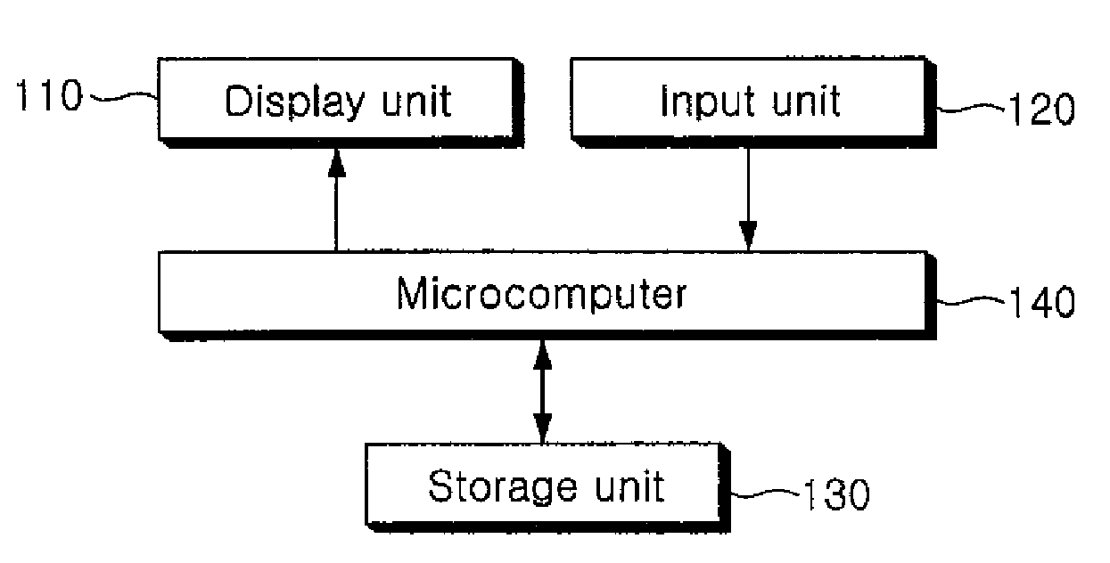
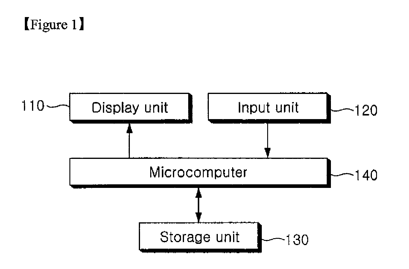
[0126]As shown in the figure, the basic configuration of this embodiment is same as that of the second embodiment. That is, the control unit for a refrigerator according to this embodiment also comprises a display unit 510 for displaying a main screen and a setting screen 515, and an input unit 520 for receiving operation signals for operations of the refrigerator.

[0127]In this embodiment, function display bars 517 and 519 are displayed on both sides of the setting screen 515 displayed on the display unit 510. The input unit 520 comprises three menu setting buttons 521, 522 and 523 and three detail setting buttons 524, 525 and 526, which are provided vertically at regular intervals on...

fourth embodiment

[0129]Next, a control unit for a refrigerator according to the present invention will be described in further detail with reference to the accompanying drawings.

[0130]FIG. 15 is a front view showing a refrigerator provided with the control unit for a refrigerator according to the fourth embodiment of the present invention, FIGS. 16 to 18 are views schematically showing a process of displaying menus on a display unit in the fourth embodiment of the present invention.

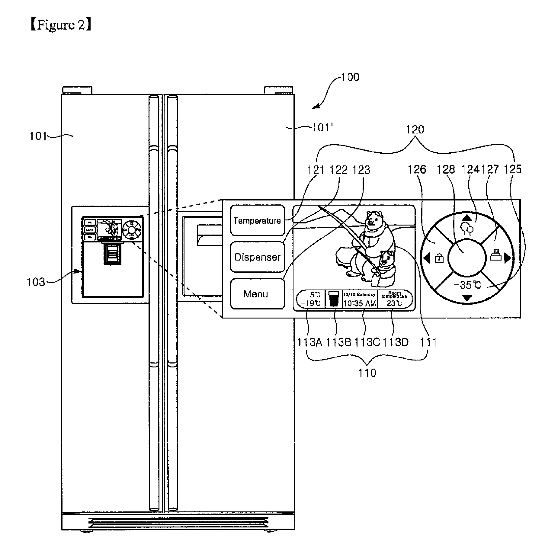
[0131]As shown in the figure, the refrigerator is provided with a pair of doors 601 and 601′ for selectively opening and closing a storage space, i.e., a freezing chamber and a refrigerating chamber, provided inside a main body 600 of the refrigerator. Any one door 601 of the doors 601 and 601′ is provided with a dispenser 603. The dispenser 603 is to dispense water or ice to the outside without opening the door 601.

[0132]The dispenser 603 is provided with a display unit 610 and an input unit 620. The display unit 610 is ...


PUM


Abstract

The present invention relates to a control unit for a refrigerator and a method of controlling the same. A control unit for a refrigerator according to the present invention comprises an input means for receiving an operation signal for setting a service mode of a dispenser provided at the refrigerator; a storage means for storing a plurality of mode image data corresponding to the service mode of the dispenser; a display means for displaying mode images of the mode image data; and a control means for performing control such that mode image data corresponding to the service mode of the dispenser are read from the storage means according to an operation signal received by the input means and a mode image corresponding to the service mode of the dispenser is displayed on the display means. According to the present invention, there are advantages in that more various menus can be displayed in different manners, and the configuration of the input unit is simplified and thus can be more conveniently used.

Description

TECHNICAL FIELD[0001]The present invention relates to a refrigerator, and more particularly, to a control unit for a refrigerator, which receives a variety of operation signals for controlling operations of the refrigerator and causes a variety of information related thereto to be externally displayed, and a method of controlling the control unit.BACKGROUND ART[0002]Generally, a control unit for a refrigerator comprises an input unit for receiving a variety of operation signals for operations of the refrigerator, a display unit for externally displaying a variety of information on the operations of the refrigerator, and a controller for controlling the input unit and the display unit. FIGS. 20 and 21 are front views schematically showing conventional control unites for refrigerators.[0003]As shown in FIG. 20, a display unit 10 displays a variety of information on operations of a refrigerator, such as set temperatures of a freezing chamber and a refrigerating chamber, and a service m...

Claims


Application Information

Patent Timeline
Patent Type & Authority Applications(United States)
IPC IPC(8): G06F3/048
CPCF25C2400/10F25D23/126F25D29/00F25D2400/30F25D2400/361F25D2500/06F25D2700/14
Inventor LEE, IK-KYULEE, SUNG-AEJEON, JI-WON
Owner LG ELECTRONICS INC
Why Eureka
Try Eureka