Resonant Difference-Frequency Atomic Force Ultrasonic Microscope

a technology of atomic force and ultrasonic microscope, which is applied in the field of scanning probe microscopy, can solve the problems of insufficient methods for assessing deeper (subsurface) features at the nanoscal

Inactive Publication Date: 2008-12-04
NASA
View PDF17 Cites 34 Cited by
  • Summary
  • Abstract
  • Description
  • Claims
  • Application Information

AI Technical Summary

Benefits of technology

[0007]In one embodiment of the invention, an atomic force microscope is provided for examining sub-surface features embedded in a matrix material of a sample. The microscope comprises: (1) a cantilever arm having a plurality of contact resonance frequencies; (2) a probe secured to a free end of the cantilever arm; (3) an oscillator drive coupled to the cantilever arm and configured to oscillate the cantilever arm at a first frequency in response to a first drive signal; (4) a frequency generator located on an opposite side of the sample from the probe, the frequency generator configured to generate a signal at a second frequency in response to a second drive signal, the second frequency differing from the first frequency by an amount substantially equal to one of the contact resonance frequenci

Problems solved by technology

Because of this, keeping the probe tip close enough to the sample for short-range forces to become detectable while preventing the tip from sticking to the surface presents a major hurdle for the

Method used


Image

  • Resonant Difference-Frequency Atomic Force Ultrasonic Microscope
  • Resonant Difference-Frequency Atomic Force Ultrasonic Microscope
  • Resonant Difference-Frequency Atomic Force Ultrasonic Microscope

Examples


Embodiment Construction

[0015]The present invention will now be described more fully hereinafter with reference to the accompanying drawings, in which preferred embodiments of the invention are shown. This invention may, however, be embodied in many different forms and should not be construed as limited to the embodiments set forth herein; rather, these embodiments are provided so that this disclosure will be thorough and complete, and will fully convey the scope of the invention to those skilled in the art. Like numbers refer to like elements throughout.

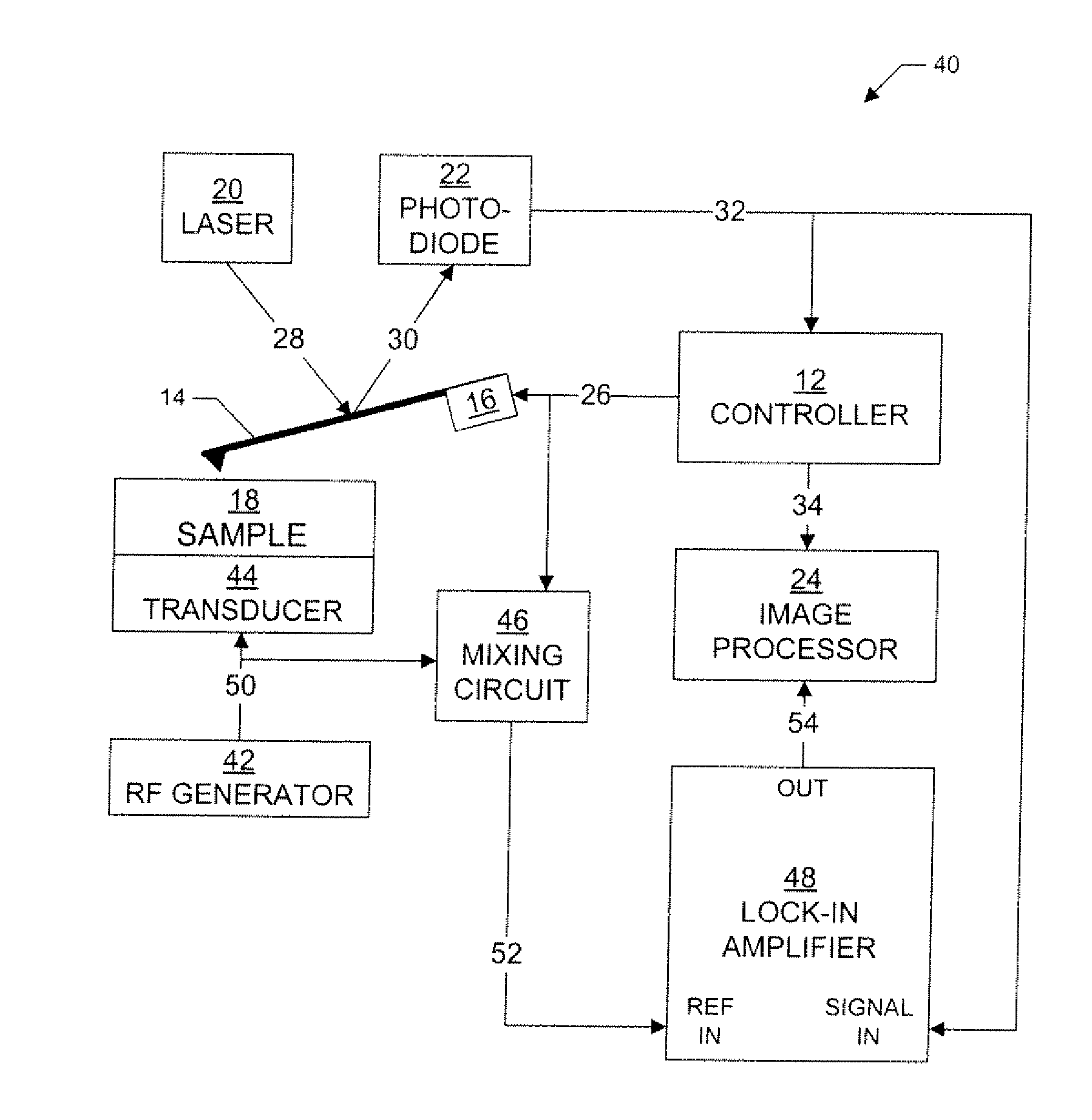
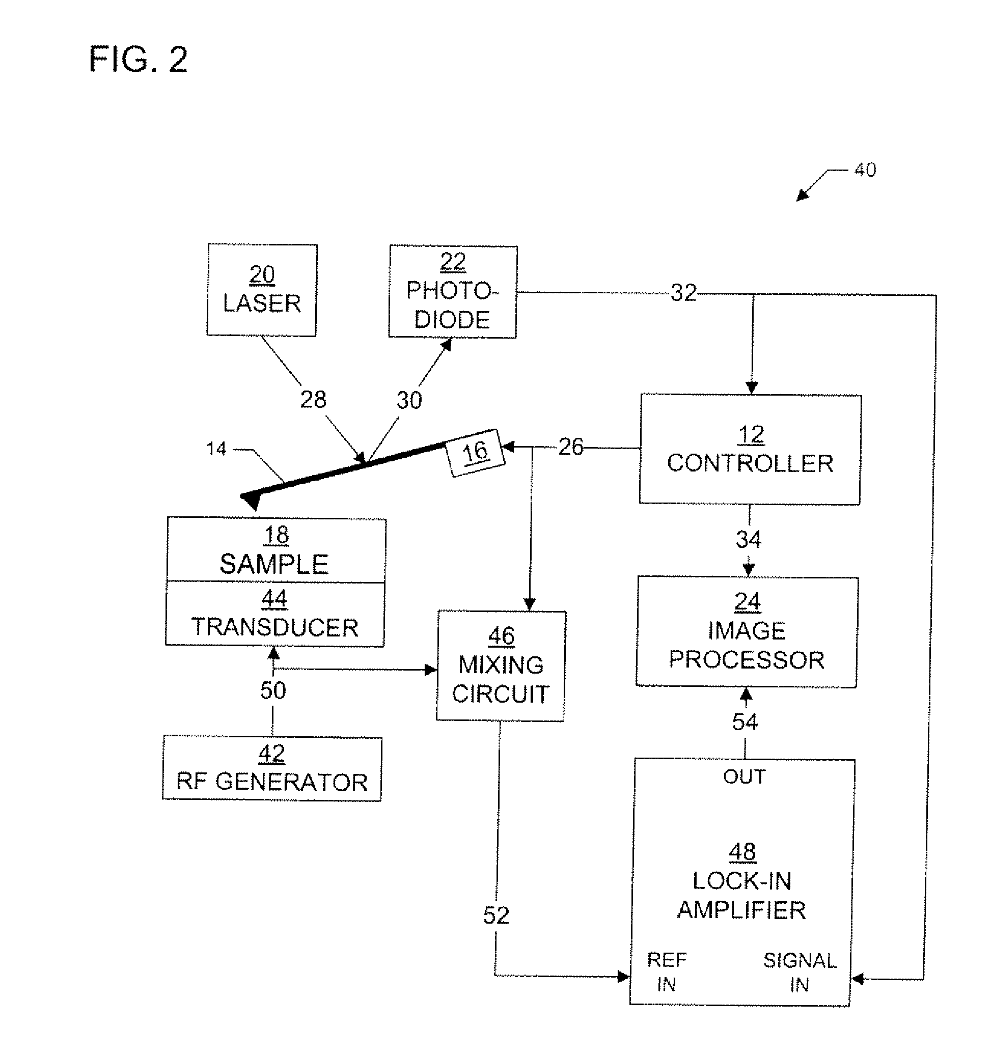
[0016]Resonant difference-frequency atomic force ultrasonic microscopy (RDF-AFUM) of embodiments of the invention employs an ultrasonic wave launched from the bottom of a sample while the cantilever of an atomic force microscope, driven at a frequency differing from the ultrasonic frequency by one of the contact resonance frequencies of the cantilever, engages the sample top surface. At high drive amplitudes of the ultrasonic wave or cantilever (or both), ...


PUM


Abstract

A scanning probe microscope and methodology called resonant difference-frequency atomic force ultrasonic microscopy (RDF-AFUM), employs an ultrasonic wave launched from the bottom of a sample while the cantilever of an atomic force microscope, driven at a frequency differing from the ultrasonic frequency by one of the contact resonance frequencies of the cantilever, engages the sample top surface. The nonlinear mixing of the oscillating cantilever and the ultrasonic wave in the region defined by the cantilever tip-sample surface interaction force generates difference-frequency oscillations at the cantilever contact resonance. The resonance-enhanced difference-frequency signals are used to create images of nanoscale near-surface and subsurface features.

Description

ORIGIN OF THE INVENTION[0001]This invention was made in part by an employee of the United States Government and may be manufactured and used by or for the Government of the United States of America for governmental purposes without the payment of any royalties thereon. This application claims the benefit of U.S. Patent Application No. 60 / 940,980, filed May 31, 2007, which is incorporated by reference herein in its entirety.FIELD OF THE INVENTION[0002]The present invention generally relates to scanning probe microscopy, and, more particularly, relates to resonant difference-frequency atomic force ultrasonic microscopy for creating images of nanoscale near-surface and subsurface features of a sample.BACKGROUND OF THE INVENTION[0003]Scanning probe microscopy (SPM) is a branch of microscopy that forms images of surfaces of a sample or specimen using a physical probe that scans the sample. An image of the surface is obtained by mechanically moving the probe in a raster (line by line) sca...

Claims


Application Information

Patent Timeline
IPC IPC(8): G01B5/28
CPCG01Q60/32B82Y35/00
Inventor CANTRELL, JOHN H.CANTRELL, SEAN
Owner NASA
Why Eureka
Try Eureka