Continuous electrolytic refining device for metal uranium

a technology of electrolysis refining and metal uranium, which is applied in the direction of electrolysis process, electrolysis components, cells, etc., can solve the problems of large quantity of products which cannot be obtained continuously, tissue which is difficult to detach, and inability to achieve continuous operation, etc., to achieve high purity

Inactive Publication Date: 2008-12-04
KOREA HYDRO & NUCLEAR POWER CO LTD +1
View PDF12 Cites 12 Cited by
  • Summary
  • Abstract
  • Description
  • Claims
  • Application Information

AI Technical Summary

Benefits of technology

[0019]Accordingly, the present invention has been made keeping in mind the above problems occurring in the related art, and an object of the present invention is to provide a continuous electrolytic ref

Problems solved by technology

However, the electrolytic refining process of metal uranium using the conventional electrolytic refining device of metal uranium has drawbacks that an electrolytic reaction must be stopped to periodically collect metal uranium deposited on to a cathode, and due to a long operation time to collect electrodeposits, it is impossible to do a continuous operation.
Therefore a large quantity of products cannot be obtained in a short time.
However, the refining device has only a part of the metal uranium deposited on a cathode detached, and the remnant electrodeposits keep sticking on the surface of the cathode, and are gradually changed into a dense tissue which is difficult to detach.
The above stripping process has drawbacks that a lot of electricity is consumed, the deposition efficiency is deteriorated and that the device becomes complicated.
Furthermore, there occurs a problem that the electrolysis must be stopped in order to collect electrodeposit

Method used


Image

  • Continuous electrolytic refining device for metal uranium
  • Continuous electrolytic refining device for metal uranium
  • Continuous electrolytic refining device for metal uranium

Examples


Embodiment Construction

[0040]Hereinafter, embodiments of a continuous electrolytic refining device according to the present invention will be described in detail with reference to the attached drawings for those having ordinary skill in the arts to which the present invention belongs to easily execute. However, the present invention may be realized in various different shapes and is not limited to the embodiments described herein.

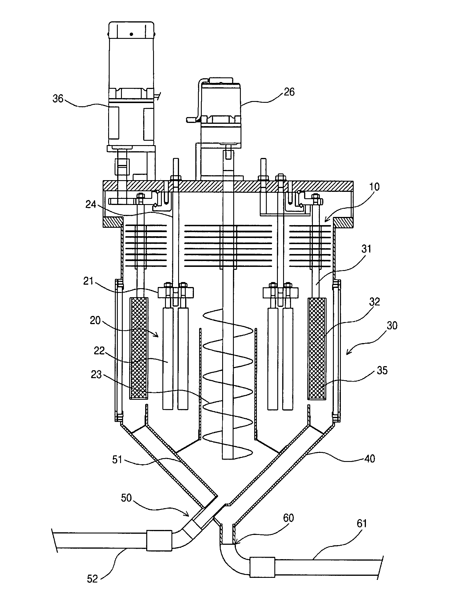
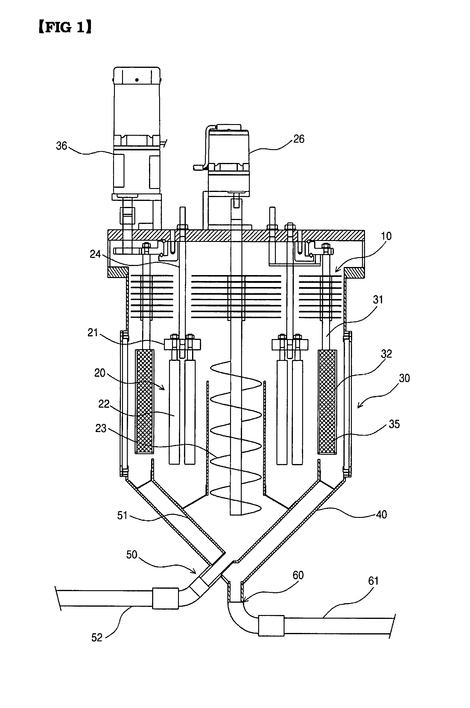
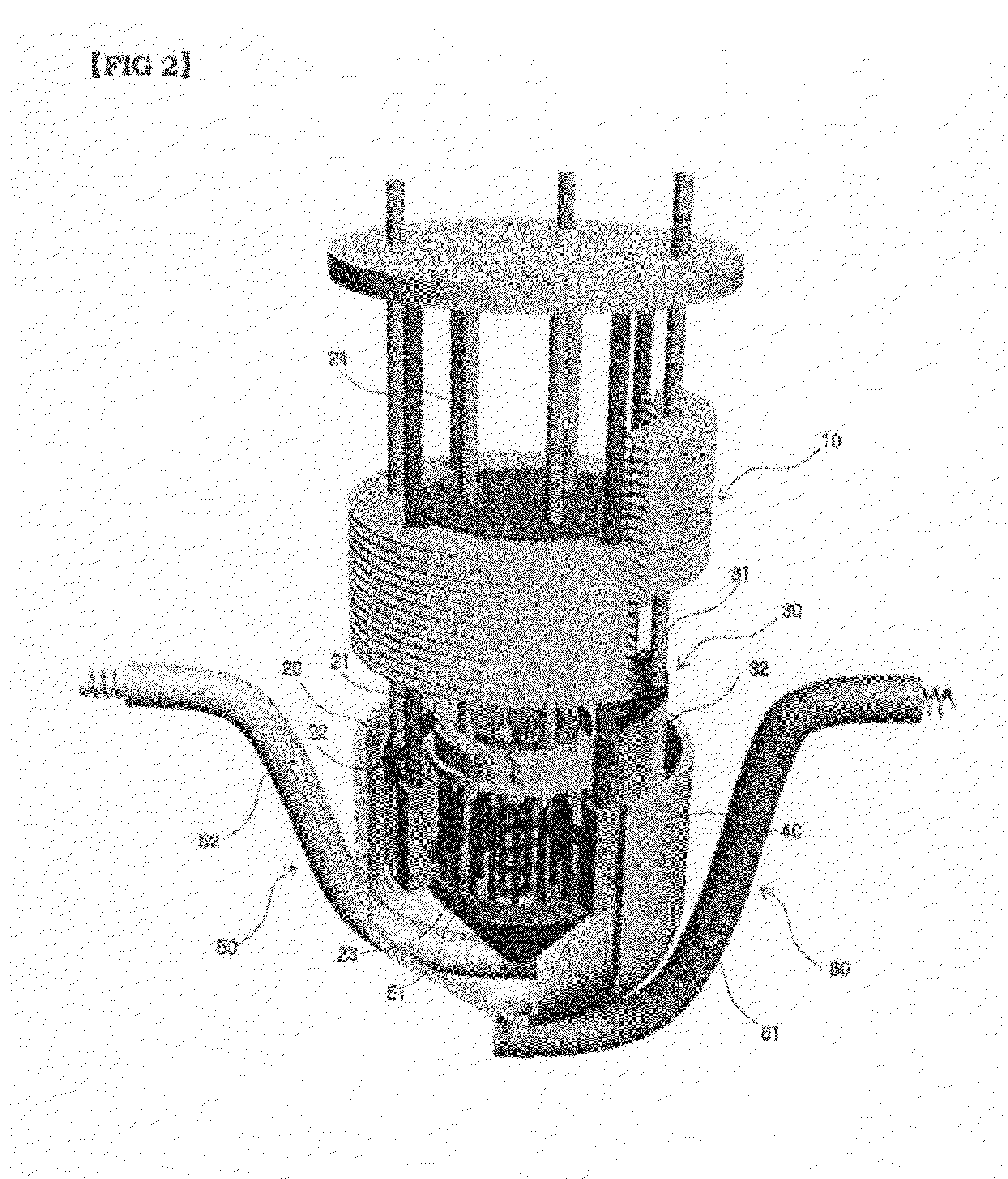
[0041]FIG. 1 is a cross-sectional view showing a continuous electrolytic refining device of metal uranium in accordance with an embodiment of the present invention, and FIG. 2 is a partial cut-off perspective view stereographically showing the continuous electrolytic refining device of metal uranium shown in FIG. 1.

[0042]Referring to FIGS. 1 and 2, the continuous electrolytic refining device for metal uranium in accordance with the present embodiment comprises a cathode section (20) fixed to the lower side of a heat radiation plate (10), an anode section (30) receiving the used n...


PUM

PropertyMeasurementUnit
Angleaaaaaaaaaa
Mesh sizeaaaaaaaaaa
Flexibilityaaaaaaaaaa

Abstract

Disclosed herein is a continuous electrolytic refining device for metal uranium, the device comprising a cathode section fixed to the lower side of the heat radiation plate, and having a plurality of graphite cathodes; an anode section encompassing the cathode section to face the cathode section, rotatably fixed to the lower side of the heat radiation plate, and receiving the used nuclear fuel; an electrolytic cell receiving the cathode section and the anode section and filled with electrolytes so as to sink the cathode section and the anode section; an uranium collecting section collecting metal uranium deposited on and detached from the graphite cathode in the lower side of the cathode section inside the electrolytic cell and withdrawing the collected metal uranium to the outside of the electrolytic cell; and a transition metal collecting section coupled with the lower side of the electrolytic cell to withdraw the transition metal particles released from the anode section and collected in the lower side of the electrolytic cell, in order to collect high pure uranium deposits and metal transition elements created in an electrolysis process without stopping an electrolysis process, not including a scrapping process.

Description

BACKGROUND OF THE INVENTION[0001]1. Field of the Invention[0002]The present invention relates generally to electrolytic refining devices of metal uranium, and more particularly to a continuous electrolytic refining device for metal uranium without stopping an electrolytic process in collecting uranium deposits and metal transition element generated in the electrolytic process.[0003]2. Description of the Related Art[0004]As well-known to the public, the conventional electrolytic refining device of metal uranium used as a nuclear fuel consists of an anode basket including segments of a metal fuel and an iron-based cathode on which pure uranium is deposited after having been used in a melted salt about 500° C. where uranium chloride is molten.[0005]When refining metal uranium using the conventional electrolytic refining device of metal uranium, if electric power is applied, the uranium chloride in the molten salt is reduced to be deposited on a cathode, and chloride ions separated in t...

Claims


Application Information

Patent Timeline
IPC IPC(8): C25C7/00
CPCC25C3/34C25C7/005C25C1/22C25C3/00C25C7/00
Inventor LEE, JONG-HYEONKANG, YOUNG-HOHWANG, SUNG-CHANLEE, HAN-SOOKIM, EUNG-HOPARK, SEONG-WON
Owner KOREA HYDRO & NUCLEAR POWER CO LTD
Why Eureka
Try Eureka