Cryogenic Pipeline Configurations and Methods

a technology of cryogenic pipelines and configurations, applied in mechanical equipment, liquefaction, lighting and heating equipment, etc., can solve the problems of significant thermal stress, new difficulties arose with such solutions, and cryogenic transport of fluids and/or gases

Active Publication Date: 2008-12-04
FLUOR TECH CORP
View PDF12 Cites 12 Cited by
  • Summary
  • Abstract
  • Description
  • Claims
  • Application Information

AI Technical Summary

Problems solved by technology

Cryogenic transport of fluids and/or gases in pipelines is often problematic as the low temperature of fluids or gases entering the pipeline leads to substantial shrinkage of most pipe materials, thereby generating significant thermal stress.
While numerous attempts have been made to accommodate for thermal stress, new difficulties arose with such solutions.
However, all or almost all of the known insulating materials fail to alleviate thermal stress that develops as the cryogenic material enters the pipeline.
Therefore, even though insulating reduce cold loss to at least some degree, insulating materials fail to provide any structural support to the pipe-in-pipe configuration.
However, such stabilization is typically still insufficient, especially for relatively long pipelines.
Unfortunately, while such co

Method used


Image

  • Cryogenic Pipeline Configurations and Methods
  • Cryogenic Pipeline Configurations and Methods
  • Cryogenic Pipeline Configurations and Methods

Examples


Embodiment Construction

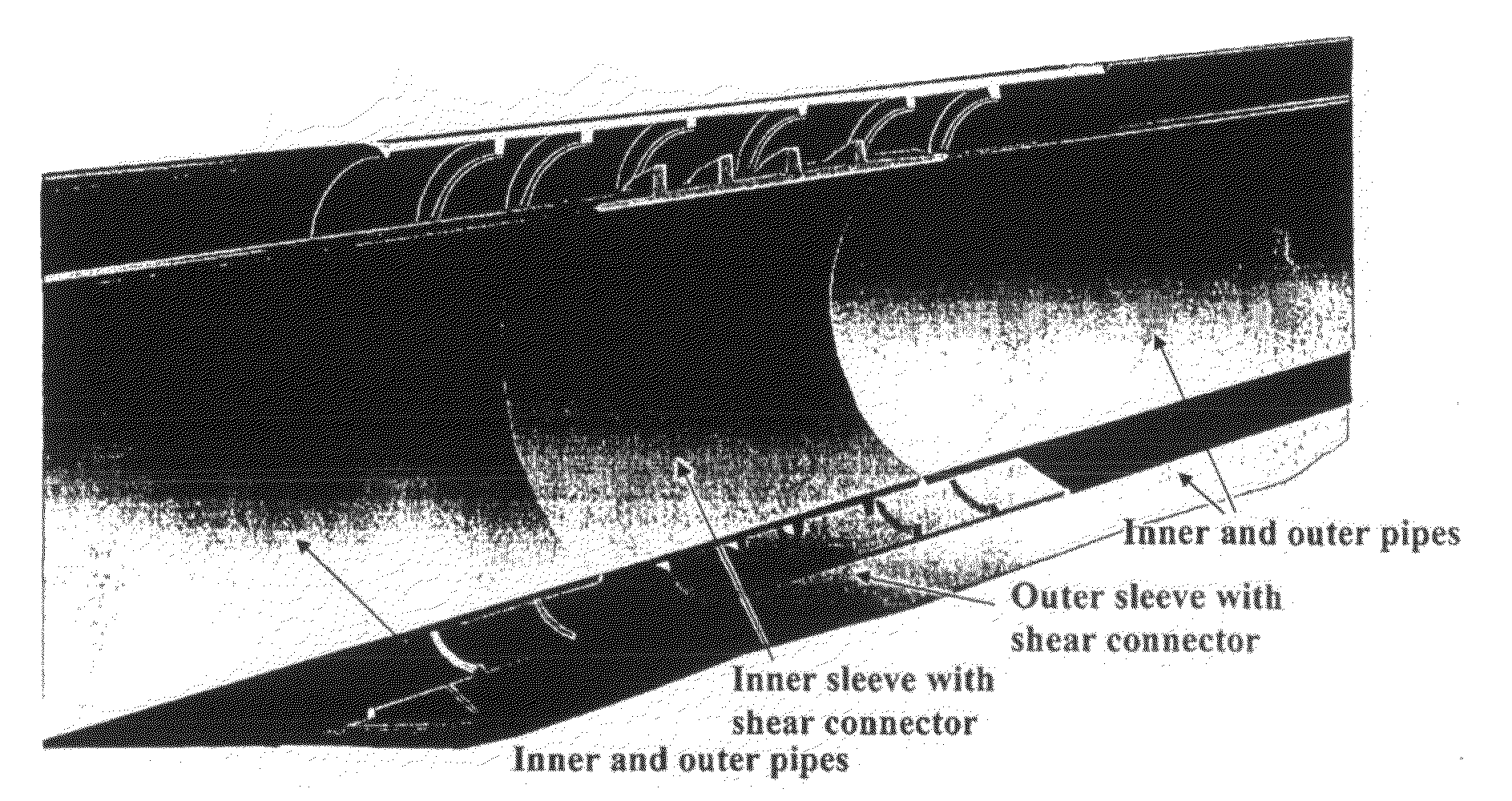
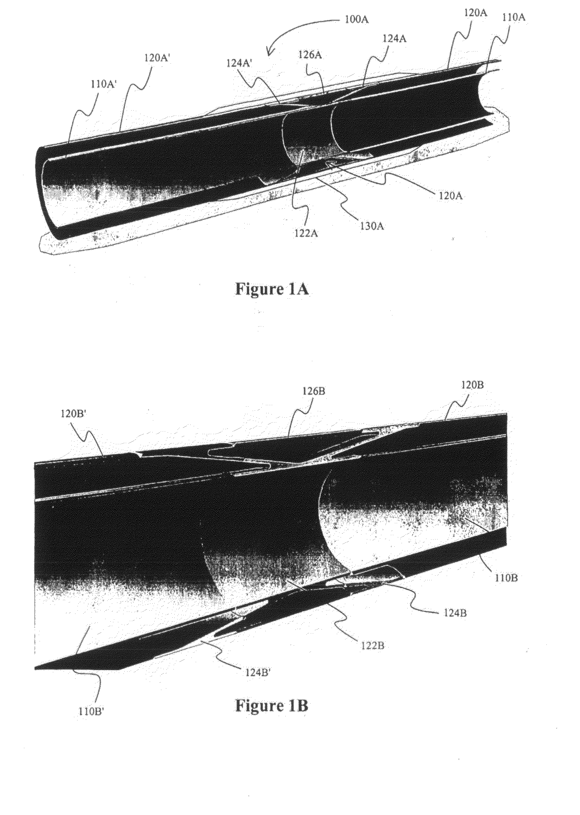
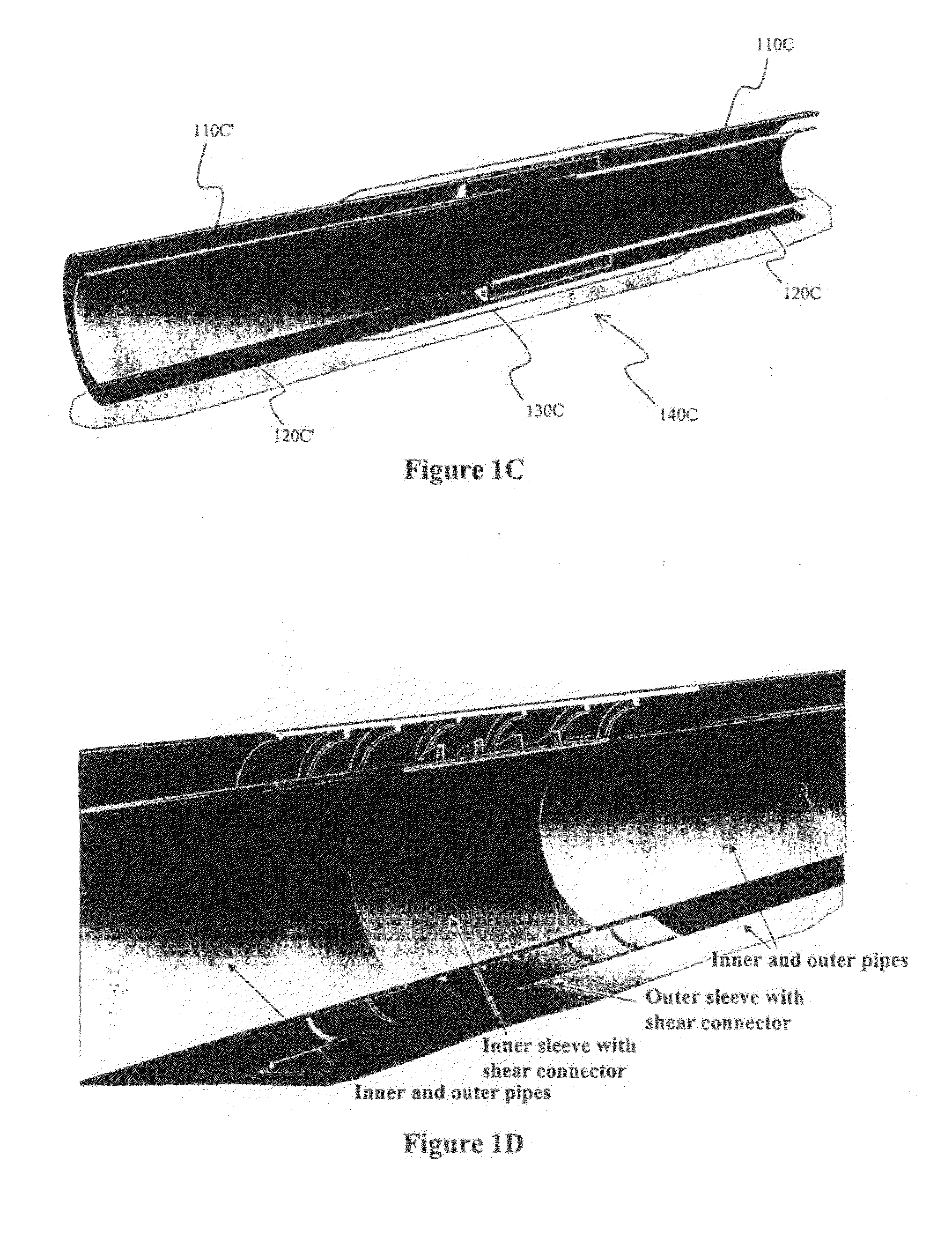
[0022]The inventors discovered that pipelines, and especially those transporting material at sub-ambient temperature (e.g., cryogenic material) can be constructed in a manner such that the pipeline has both increased mechanical stability and desirable thermal insulation while maintaining a mechanically simple structure, which is relatively inexpensive to manufacture and install.

[0023]In particularly preferred aspects of the inventive subject matter, a cryogenic pipeline is manufactured from conventional materials. For example, the product pipe in a pipe-in-pipe pipeline can be manufactured from steel rated for cryogenic service (e.g., 9% Nickel steel), while the jacket pipe can be manufactured from carbon steel. Thermal insulation in such configurations is preferably a high performance nanoporous aerogel product, typically about 2 inches thick, in blanket form installed within the annular space at ambient pressure.

[0024]In one exemplary aspect of the inventive subject matter, a plur...


PUM


Abstract

A pipe-in-pipe pipeline has a bulkhead that transfers thermal stress from an inner pipe to an outer pipe, wherein at least part of the bulkhead forms a conduit for a product traveling through the inner pipe. Most preferably, the pipeline is a cryogenic pipeline for transport of liquefied natural gas. Where desirable, insulating material may be disposed between the inner pipe and outer pipe, while spacers may maintain the distance between the pipes.

Description

[0001]This application claims the benefit of our U.S. provisional patent application with the Ser. No. 60 / 556,535, which was filed Mar. 26, 2004, and which is incorporated by reference herein.FIELD OF THE INVENTION[0002]Configurations and methods for pipelines in which cryogenic materials (typically at least below −200° F.) are transported.BACKGROUND OF THE INVENTION[0003]Cryogenic transport of fluids and / or gases in pipelines is often problematic as the low temperature of fluids or gases entering the pipeline leads to substantial shrinkage of most pipe materials, thereby generating significant thermal stress. While numerous attempts have been made to accommodate for thermal stress, new difficulties arose with such solutions.[0004]In most known configurations, cryogenic pipelines have a pipe-in-pipe configuration in which an outer protective pipe circumferentially encloses an inner pipeline in which the cryogenic material is transported. Thus, such systems typically include an annul...

Claims


Application Information

Patent Timeline
IPC IPC(8): F25J5/00F16L7/02F16L59/14
CPCF16L7/02F16L59/141F16L59/143
Inventor PRESCOTT, CLIFFORD NEALZHANG, JIANFENG
Owner FLUOR TECH CORP
Why Eureka
Try Eureka