Cove Illumination Module and System

a technology of illumination module and cove, which is applied in the field of lighting, can solve the problems of undesired illumination hot spots and the inability to provide environmental protection for the led light assembly

Inactive Publication Date: 2008-12-04
KONINKLIJKE PHILIPS ELECTRONICS NV
View PDF27 Cites 174 Cited by
  • Summary
  • Abstract
  • Description
  • Claims
  • Application Information

AI Technical Summary

Problems solved by technology

A cove lighting system, however, is typically not very deep resulting in a tight setback distance between the light source and the surface to be illuminated thereby typically resulting in the appearance of undesired illumination hot spots.
A cover is provided to enclose the LED light assembly, however environmental protection of the LED light assembly may not be provided due to mounting apertures being configured within both the cover and the mounting surface.

Method used


Image

  • Cove Illumination Module and System
  • Cove Illumination Module and System
  • Cove Illumination Module and System

Examples


examples

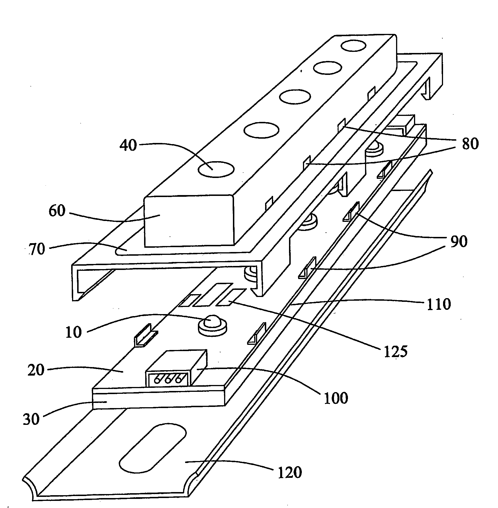
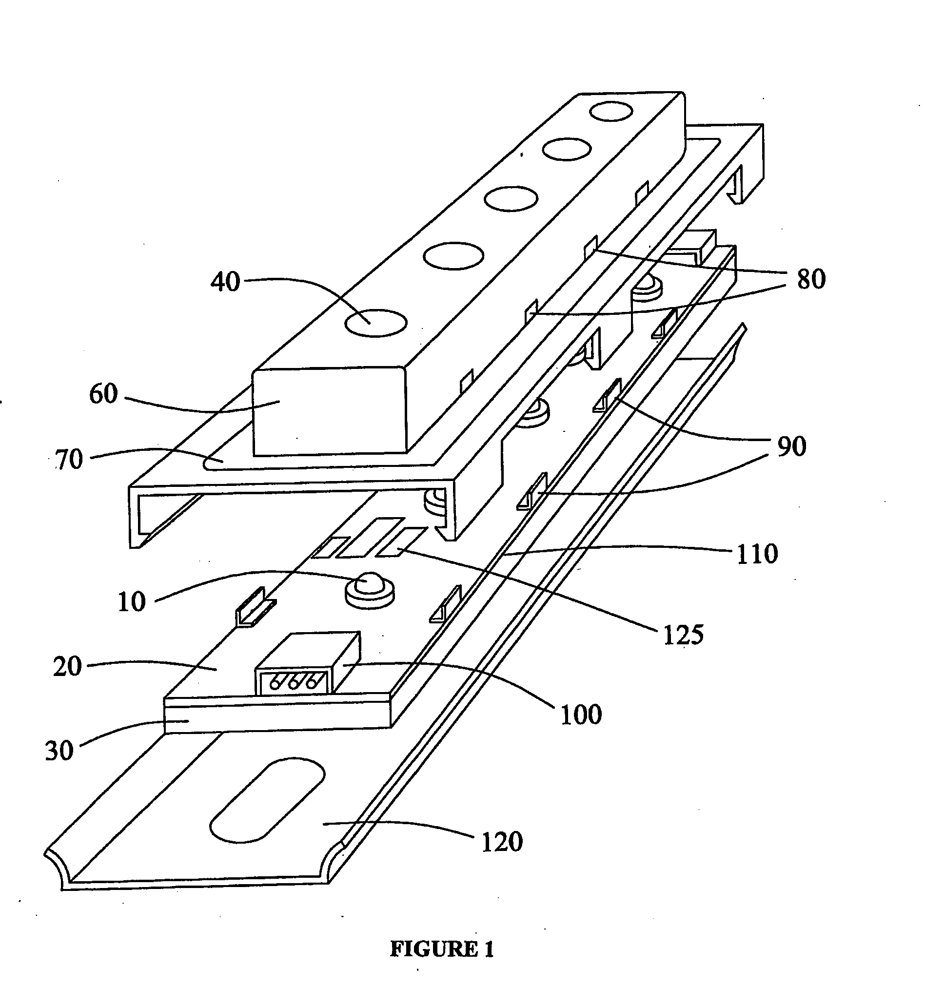
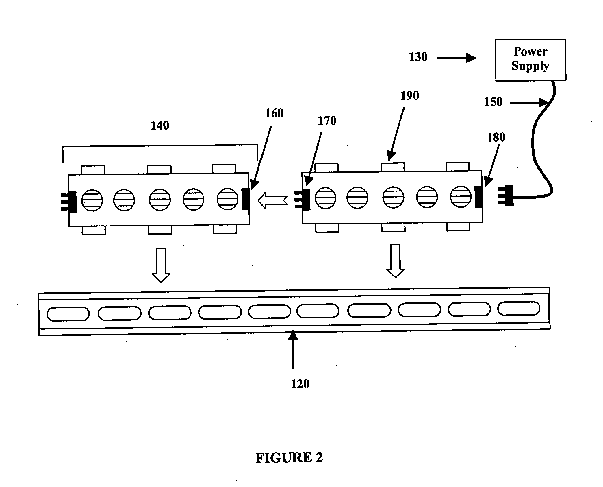
[0086]Reference is now made to FIG. 3 and FIG. 4, which illustrate a cove illumination module that comprises a tubular external housing 310 according to one embodiment of the present invention. FIG. 3 illustrates an exploded view and FIG. 4 illustrates an assembled view of the cove illumination module. The housing 310 can have any desired cross section and it can also be flexible or pliable. The illumination module also comprises light-emitting elements (not shown in FIGS. 3 and 4) which are mounted to an elongated narrow MCPCB substrate (not shown). The substrate also bears electronic drive current circuitry for the light-emitting elements that requires, for example a 24V DC power supply to power a series of interconnectible cove illumination modules. Electrical control or power connections of the substrate can be achieved via wires 305 which can be connected to insulation displacement connectors 327. An optical element 330 is positioned typically above the light-emitting elements ...


PUM


Abstract

The present invention provides a cove illumination module for use in a plurality of illumination applications wherein a particular type of cove type illumination pattern is desired due to close proximity between the cove illumination module and a to-be-illuminated surface. The cove illumination module comprises a substrate to which a plurality of light-emitting elements is operatively connected. Optionally, the substrate can form a base portion of the cove illumination module. An external housing unit is sealingly mated with the substrate in order to environmentally seal the light-emitting elements. The external housing unit comprises one or more optical elements which can shape the beams of light emitted by the light-emitting elements under operating conditions and generate a desired illumination pattern on a lit surface, thereby providing a cove type illumination pattern.

Description

FIELD OF THE INVENTION[0001]The present invention pertains to the field of lighting and in particular to a cove illumination module and system.BACKGROUND[0002]Recent advances in the development of semiconductor and organic light-emitting diodes (LEDs and OLEDs) have made these solid-state devices suitable for use in general illumination applications, including architectural, entertainment, and roadway lighting, for example. As such, these devices are becoming increasingly competitive with light sources such as incandescent, fluorescent, and high-intensity discharge lamps.[0003]Having particular regard to canopies in the sign industry, many of these canopies need to be illuminated to draw attention and attract potential customers. Some translucent or transparent canopies can effectively transmit light of various colors and can be backlit if desired. Others typically use an ACM (aluminium composite material) surface which is coloured and in order to illuminate this surface there is re...

Claims


Application Information

Patent Timeline
Patent Type & Authority Applications(United States)
IPC IPC(8): F21S15/00
CPCF21S4/003F21V15/01F21V15/015F21V17/164F21V19/001F21V21/005F21V23/06F21V31/005F21Y2101/02F21Y2103/003G09F13/02H01R25/162F21S4/20F21Y2103/10F21Y2115/10H05K2203/167
Inventor KAN, PETERWESTON, ADRIANMATHESON, GEORGECAMPBELL, DAMONSCHMEIKAL, LAWRENCEFLOOD, STEPHEN
Owner KONINKLIJKE PHILIPS ELECTRONICS NV
Why Eureka
Try Eureka