
Power Management System and Method For Photographic Wireless Communication

a technology of power management system and wireless communication, applied in the field of photographic wireless communication, can solve the problems of affecting the strength of the mounting, and the battery can be quickly drained of power

Inactive Publication Date: 2008-12-04
LAB PARTNERS ASSOC INC
View PDF26 Cites 68 Cited by
  • Summary
  • Abstract
  • Description
  • Claims
  • Application Information

AI Technical Summary

Problems solved by technology

These batteries may be large and add size and weight to the device, which can impact the strength of the mounting required to affix the device to the camera body.
Additionally, the battery can be drained quickly of power when the wireless device is powered on, partly due to the high power requirements of some transmitter and receiver circuitry.
Such a device likely would negatively impact a photographers ability to rapidly move from one photographing scenario to another where the shutter speed of the camera body changed.

Method used


Image

  • Power Management System and Method For Photographic Wireless Communication
  • Power Management System and Method For Photographic Wireless Communication
  • Power Management System and Method For Photographic Wireless Communication

Examples


Embodiment Construction

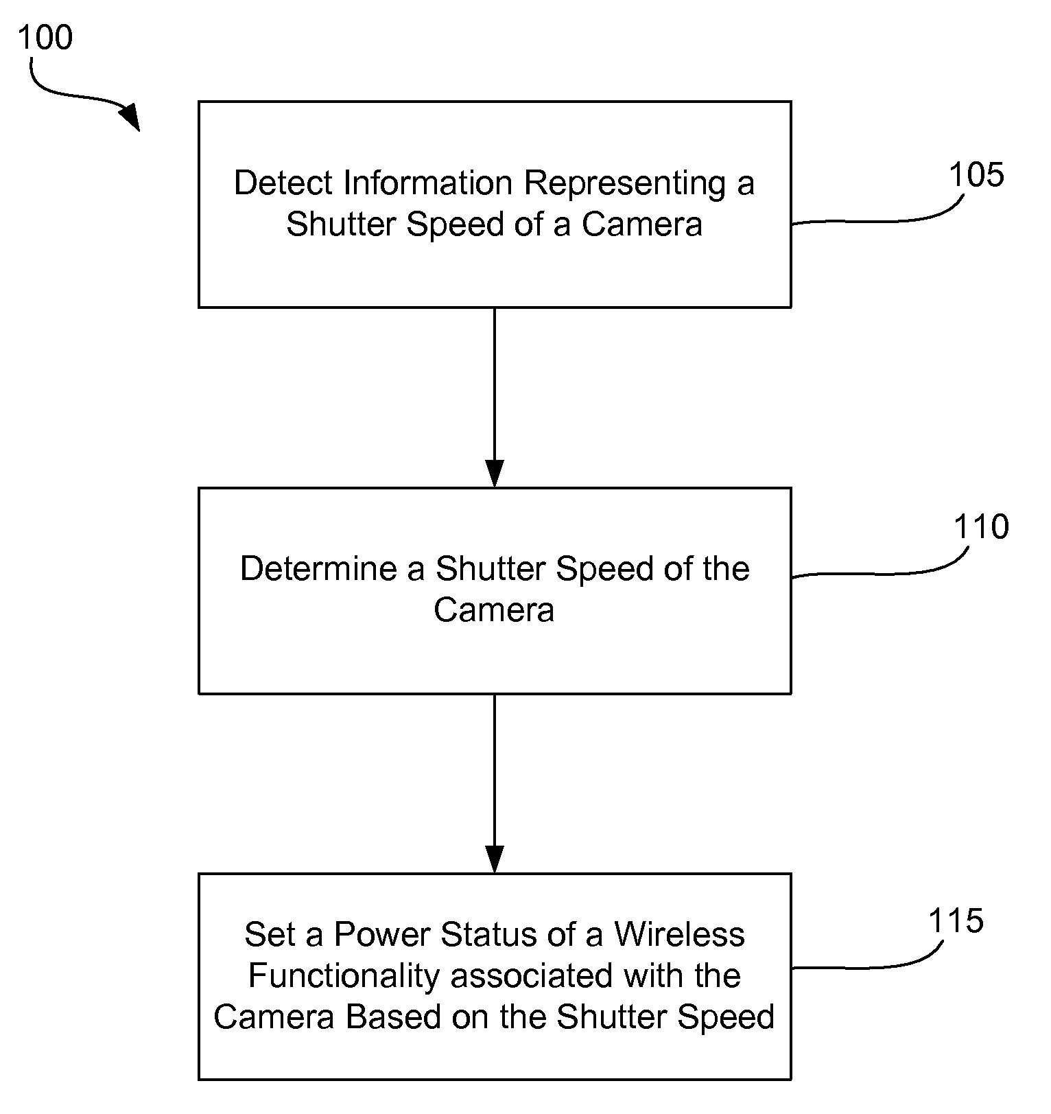
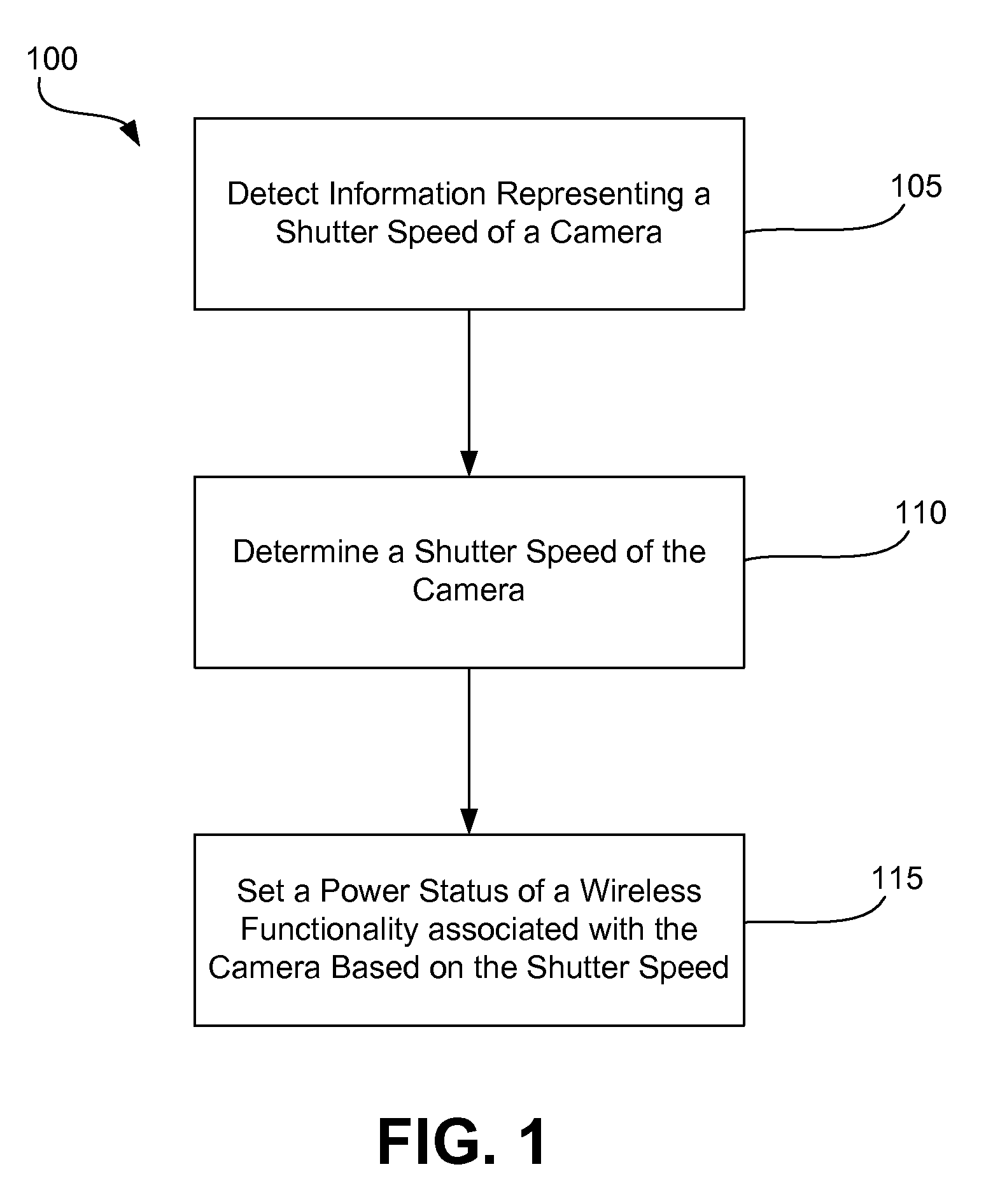
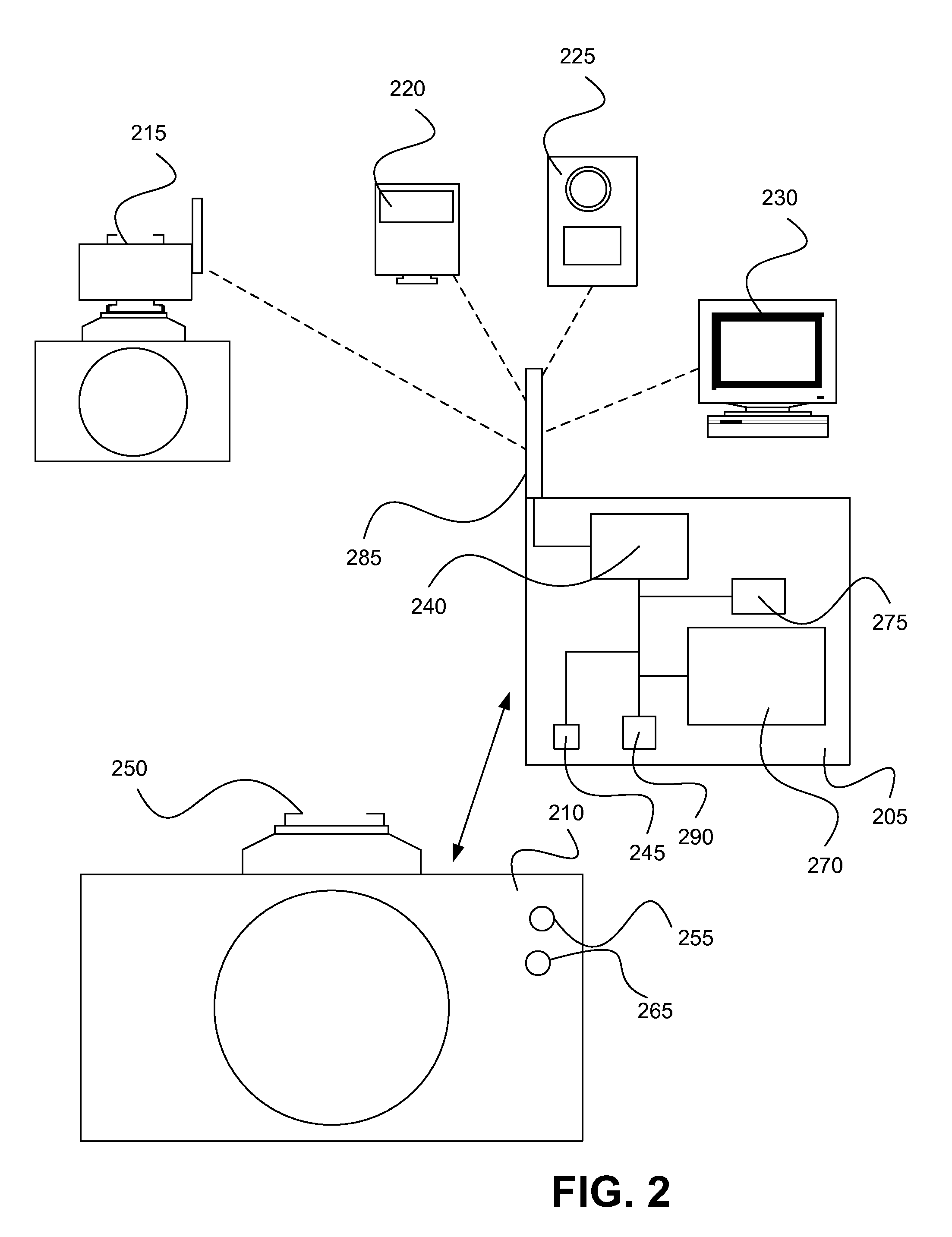
[0027]FIG. 1 illustrates one implementation of a method 100 for setting a power status of a wireless communication functionality associated with a camera based on the shutter speed of the camera. At step 105, a wireless communication functionality receives (e.g., detects) information representing a shutter speed of an associated camera. Information representing a shutter speed of a camera may be any information (e.g., data) provided by the camera to a wireless communication functionality from which a shutter speed of the camera may be determined. A shutter speed is an indication relative to the time period for which a camera will acquire an image. For example, in a camera that includes an actual shutter mechanism a shutter speed may be related to the amount of time for which the shutter is open (e.g., the time for which light is allowed to pass to a film or other light sensitive material, such as a CCD in a digital camera). In another example, a shutter speed may be related to the a...


PUM


Abstract

A system and method for setting the power operating condition of a photographic wireless communication device. An information representing a shutter speed of a camera body is detected from the camera body. A shutter speed of the camera body is determined from the information representing a shutter speed. The power operating condition of the photographic wireless communication device is automatically set based on the shutter speed of the camera body.

Description

RELATED APPLICATION DATA[0001]This application claims the benefit of priority of U.S. Provisional Patent Application Ser. No. 60 / 940,694, filed May 29, 2007, and titled “Power Management System and Method for Photographic Wireless Communication.” This application also claims the benefit of priority of U.S. Provisional Patent Application Ser. No. 61 / 030,558, filed Feb. 21, 2008, and titled “Photographic Wireless Communication for Lighting Device Control. Each of these applications is incorporated by reference herein in its entirety.[0002]This application is related to commonly-owned and copending U.S. patent application Ser. No. 12 / 129,402, filed by Applicant, James E. Clark, on May 29, 2008, and titled “System and Method for Maintaining Hot Shoe Communications Between a Camera and a Wireless Device.”FIELD OF THE INVENTION[0003]The present invention generally relates to the field of photographic wireless communication. In particular, the present invention is directed to a power manag...

Claims


Application Information

Patent Timeline
Patent Type & Authority Applications(United States)
IPC IPC(8): G03B17/00
CPCG03B17/00H04N5/23203H04N5/23241H04N23/66H04N23/651
Inventor CLARK, JAMES E.
Owner LAB PARTNERS ASSOC INC
Learn More