

Multi-Unit Cosmetic Applicator
a cosmetic applicator and multi-unit technology, applied in the field of cosmetic applicators, can solve the problems of incompatibility of cosmetic agents being used
- Summary
- Abstract
- Description
- Claims
- Application Information
AI Technical Summary
Problems solved by technology
Method used
Image

Examples
first embodiment
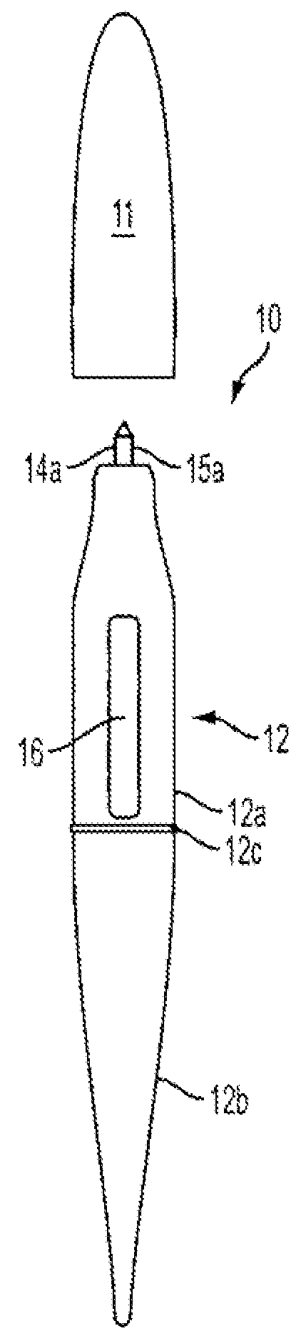
[0028]With respect to FIGS. 1 and 2, in the present invention, a multi-unit cosmetic applicator includes a first cosmetic unit and a second cosmetic unit that is movable with respect to the first cosmetic unit from a stored position to an advanced position via a slide assembly.
[0029]Herein, a “stored position” is when the second cosmetic unit is retracted in the housing, while an “advanced position” is when a user accessible portion, of any length, of the second cosmetic unit is extended beyond the housing so that the user can place the cosmetic agent comprised in the cosmetic unit onto their body.
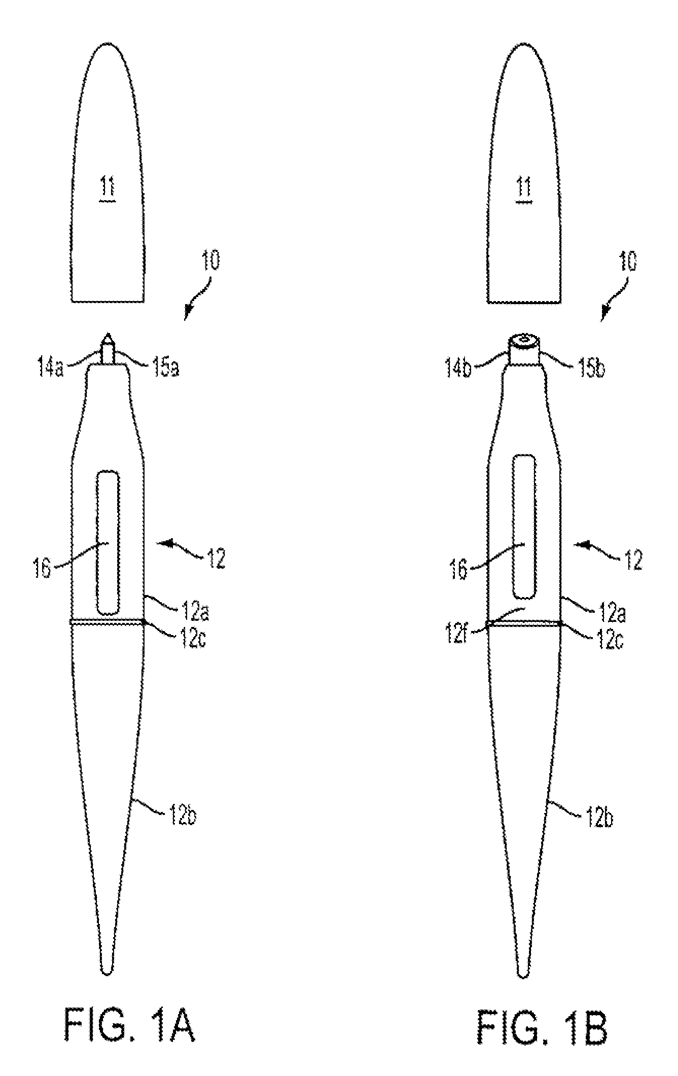
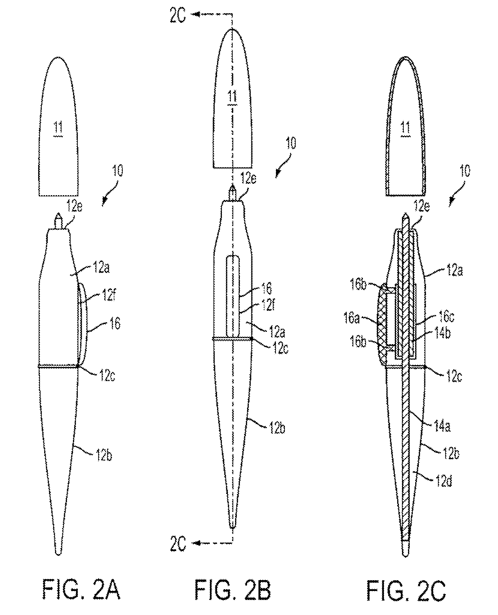
[0030]Therein, FIGS. 1a and 1b are front perspective views of a multi-unit cosmetic applicator 10 in accordance with a first embodiment of the invention. FIGS. 2a-2c are, respectively, a right-side view of multi-unit cosmetic applicator 10, a front view of multi-unit cosmetic applicator 10, and a cross-sectional view of multi-unit cosmetic applicator 10 taken along line B-B of FIG. 2b.
[00...
second embodiment
[0043]With respect to FIGS. 3 and 4, in the present invention, a multi-unit cosmetic applicator includes a first housing portion that rotates relative to a second housing portion and advances a second cosmetic agent relative to a first cosmetic agent from a stored position to an advanced position.
[0044]Therein, FIGS. 3a and 3b are perspective views of a multi-unit cosmetic applicator 30 in accordance with the second embodiment of the invention. FIGS. 4a-4c are, respectively, a front view of cosmetic applicator 30 in an advanced position, a cross-sectional view of cosmetic applicator 30 taken along line A-A of FIG. 4a, and a see-through view of cosmetic applicator 30 in an advanced position.
[0045]Preferably, multi-unit cosmetic applicator 30 is made of plastic, metal, and / or thermoplastic elastomers, rubber, manufactured using blow molding, and assembled by snap-fit assembly. However, any other material, manufacturing, and / or assembly method may be used. Especially desired is to have...
third embodiment
[0056]With respect to FIGS. 5 and 6, in the present invention, a multi-unit cosmetic applicator includes a first cosmetic unit and a second cosmetic unit that is movable with respect to the first cosmetic unit from a stored position to an advanced position via a push button and spring assembly.
[0057]Therein, FIGS. 5a and 5b are front perspective views of multi-unit cosmetic applicator 50 in accordance with one embodiment of the invention wherein certain portions of the housing are shown translucent. FIGS. 6a-6c are, respectively, a right-side view of multi-unit cosmetic applicator 50, a front view of multi-unit cosmetic applicator 10, and a cross-sectional view of multi-unit cosmetic applicator 50 taken along line A-A of FIG. 6b.
[0058]Preferably, multi-unit cosmetic applicator 50 is made of plastic, metal, and / or thermoplastic elastomers, rubber, manufactured using blow molding, and assembled by snap-fit assembly. However, any other material, manufacturing, and / or assembly method m...
PUM
 Abstract
Description
Claims
Application Information