Charge Bucket Loading for Electric ARC Furnace Production

Inactive Publication Date: 2008-12-04
HAGENBUCH LEROY G +1
View PDF108 Cites 11 Cited by
  • Summary
  • Abstract
  • Description
  • Claims
  • Application Information

AI Technical Summary

Benefits of technology

[0029]Because the truck with a rear eject body does not need to elevate the body to dump the load, the rear eject truck body in ejecting the load can clear overhead areas of the mill that make the process of loading the charge bucket amenable to occurring within the melt shop of the mill. By loading the charge bucket within the melt shop, there is no need for the expense of maintaining a transport machine to move the charge bucket outside the melt shop for loading. Of course, the truck with the rear eje

Problems solved by technology

Because the ejector blade pushes

Method used


Image

  • Charge Bucket Loading for Electric ARC Furnace Production
  • Charge Bucket Loading for Electric ARC Furnace Production
  • Charge Bucket Loading for Electric ARC Furnace Production

Examples


Embodiment Construction

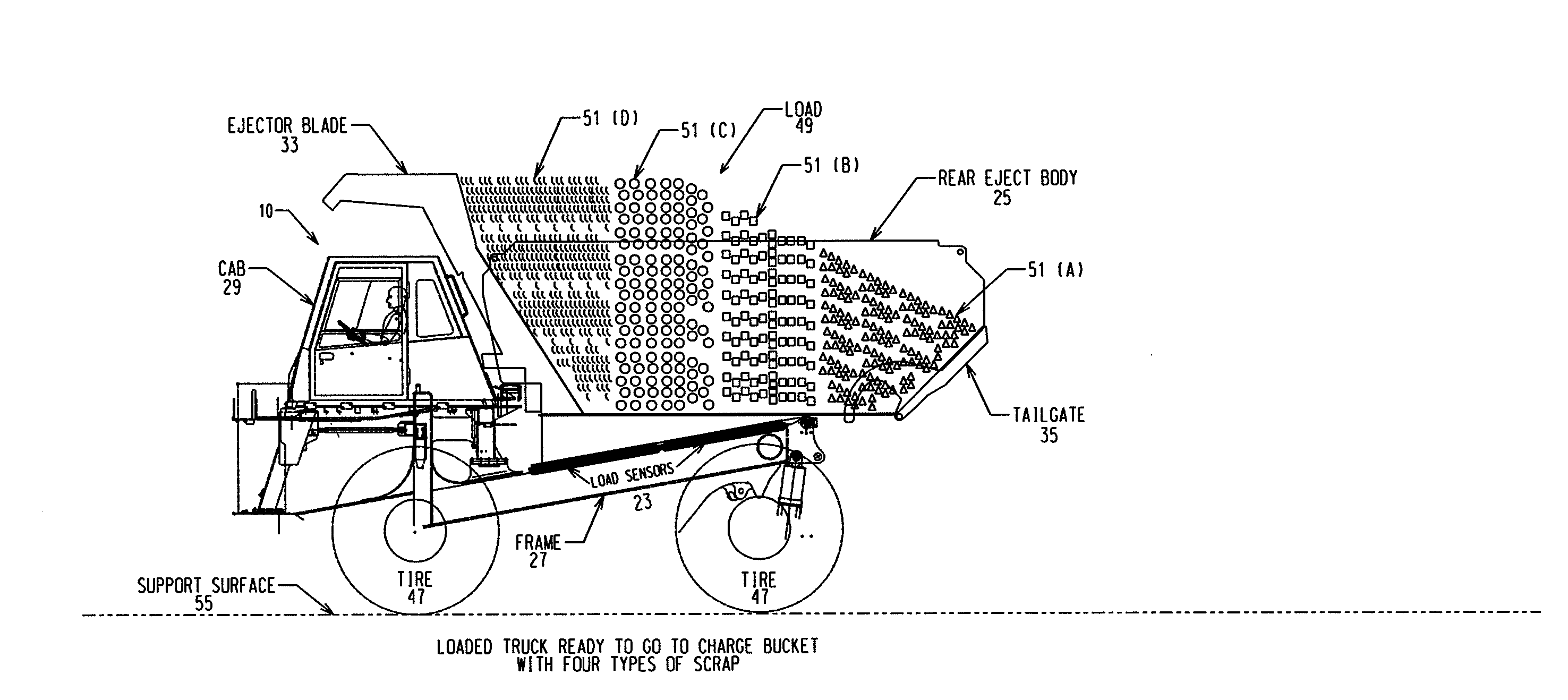
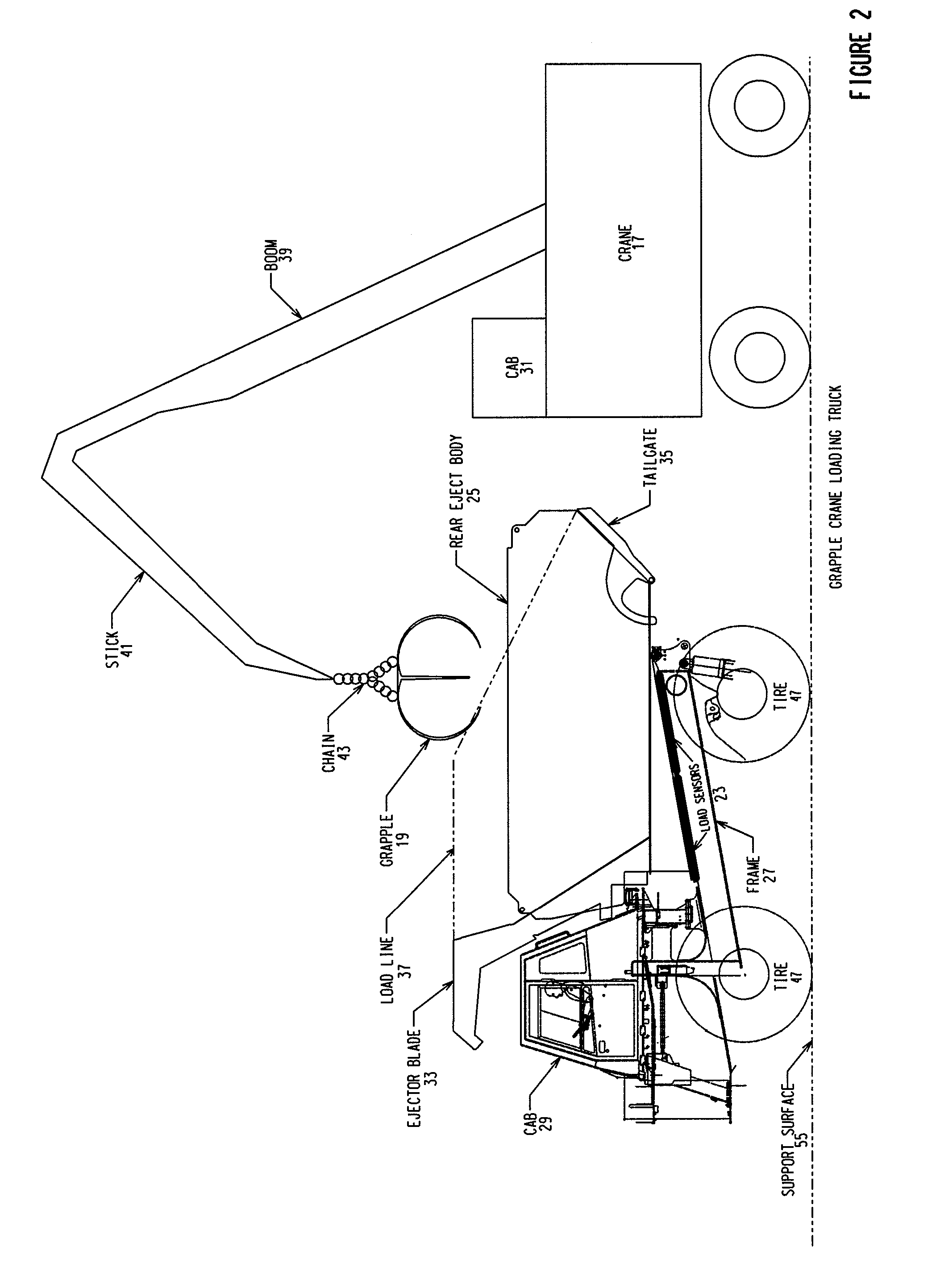
[0053]In keeping with the invention, rear eject bodies of the type illustrated and described in U.S. Pat. No. 7,326,023 are described in detail herein. U.S. Pat. No. 7,326,023 is hereby incorporated by reference for everything it describes and teaches. These types of haulage bodies as distinguished from other types of haulage bodies such as those commonly called “dump bodies” that pivot about a hinge in order to elevate the body, allowing gravity to work to dump the load it from the body. Rear eject haulage bodies of the type used in the invention do not raise the bodies to discharge the loads. Instead, a rear eject body depends on an ejector assembly that pushes the load from the front of the body toward the rear. The load falls from the body's rear edge as the ejector assembly continues to push the load toward the back edge of the body. When the ejector assembly reaches the rear end of the body, the load has been completely discharged. The ejector assembly then returns to a positi...


PUM


Abstract

Loads carried by a haulage vehicle are transferred from the vehicle to a container in a manner that maintains an ordered segmentation of materials comprising each of the loads, where each segment comprises a different type of material. The container receives the load such that each segment forms a layer in the container, which in the case of a charge bucket for feeding an electric arc furnace creates a layering of the different types of material according to a desired recipe for melting scrap metal processed by the mill incorporating the furnace. The transferring of the load is implemented by a haulage truck having a rear eject body whose ejector blade pushes the segmented load out and into the container.

Description

CROSS-REFERENCED TO RELATED APPLICATIONS[0001]This patent application is a continuation-in-part of co-pending U.S. patent application Ser. No. 11 / 945,117, filed Nov. 26, 2007, which in turn is a continuation of U.S. patent application Ser. No. 10 / 374,803 filed Feb. 25, 2003 (now U.S. Pat. No. 7,326,023). Each of co-pending U.S. patent application Ser. No. 11 / 945,117 and U.S. Pat. No. 7,326,023 is hereby incorporated by reference into this application for everything it describes and teaches without exception.[0002]This patent application also claims the benefit of U.S. Provisional Patent Application Nos. 60 / 942,185 and 60 / 943,031, filed Jun. 5 and 8, 2007, respectively, each of which is hereby incorporated by reference in its entirety for everything it describes and teaches without exception.FIELD OF THE INVENTION[0003]This invention pertains to apparatus and methods for loading steel scrap metal into charge buckets servicing electric arc furnaces of steel mills.BACKGROUND OF THE INV...

Claims


Application Information

Patent Timeline
IPC IPC(8): B60P1/00
CPCB60P1/006B60P1/26
Inventor HAGENBUCH, LEROY G.SWANK, JOSHUA J.
Owner HAGENBUCH LEROY G
Why Eureka
Try Eureka