Structure of gas sensor ensuring enhanced mechanical durability

a technology of mechanical durability and gas sensor, which is applied in the direction of structural/machine measurement, instruments, specific gravity measurement, etc., can solve problems such as sensor output errors, and achieve the effects of ensuring mechanical durability of gas sensor, avoiding terminal corrosion, and facilitating gas flow

Inactive Publication Date: 2007-09-27
DENSO CORP
View PDF6 Cites 5 Cited by
  • Summary
  • Abstract
  • Description
  • Claims
  • Application Information

AI Technical Summary

Benefits of technology

[0013] Specifically, when the gas to be measured has leaked from the housing into the inner chamber, the outer gas flow path serves to drain it outside the gas sensor through the ventilator, thereby minimizing the entrance of the gas into the porcelain insulator to avoid the exposure of the terminal to the gas. This avoids the corrosion of the terminal with the gas to ensure the mechanical durability of the gas sensor.
[0014] The recess forms a clearance between the shoulder surface of the porcelain insulator and an inner wall of the shoulder of the air cover to define a portion of the outer gas flow path, thereby facilitating ease of flow of the gas from the inner chamber to the ventilator.
[0015] The porcelain insulator surrounds the terminal of the heater, thereby minimizing direct contact of the terminal with the gas and facilitating the flow of the gas along the outer gas flow path.
[0016] In the case where the inner chamber is filled with air introduced from outside the ventilator as a reference gas used to measure the concentration of the gas, the outer gas flow path serves to minimize mixing of the gas with the air, thus ensuring the accuracy of output of the gas sensor.
[0017] In the preferred mode of the invention, the terminal of the heater has a top end and a base end which is opposite the top end and located closer to the top end of the sensor then the base end thereof. The porcelain insulator has a top end located closer to the top end of the sensor than the top end of the terminal of the heater, thereby minimizing the exposure of the terminal with the gas.
[0018] The gas sensor further comprises an inner gas flow path defined to extend from the inner chamber to outside the sensor through an inner chamber which is formed inside the porcelain insulator and through which the lead extend. The outer gas flow path has a minimum cross sectional area Sa defined perpendicular to a length thereof. The inner gas flow path has a minimum cross sectional area Sb which is defined perpendicular to a length thereof and meets a relation of Sa / Sb≧2, and preferably Sa / Sb≧5. This decreases the amount of the gas drained through the inner gas flow path to be smaller than that drained through the outer gas flow path, thereby minimizing the exposure of the terminal with the gas to avoid the corrosion of the terminal.

Problems solved by technology

The entrance of the gas into the air cover 95 will also result in a change in concentration of oxygen (O2) within an air chamber 950 defined inside the air cover 95, thus leading to an error of an output of the sensor 9.

Method used


Image

  • Structure of gas sensor ensuring enhanced mechanical durability
  • Structure of gas sensor ensuring enhanced mechanical durability
  • Structure of gas sensor ensuring enhanced mechanical durability

Examples


Embodiment Construction

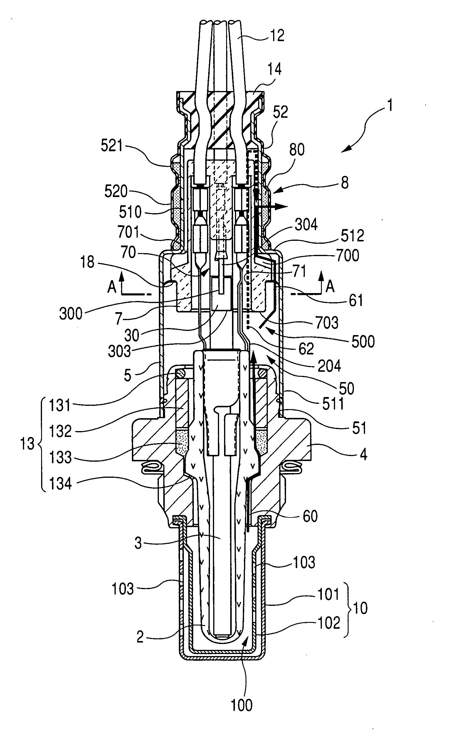
[0035] Referring to the drawings, wherein like reference numbers refer to like parts in several views, particularly to FIGS. 1 and 2, there is shown a gas sensor 1 according to the first embodiment of the invention which is designed to be installed in an exhaust pipe of an automotive internal combustion engine to measure the concentration of a component such as O2, NOx, CO, or HC of exhaust gasses for burning control of the engine.

[0036] The gas sensor 1 includes a sensor element 2, a bar-shaped ceramic heater 3 working to heat the sensor element 2 up to a desired activation temperature thereof, and a housing 4 retaining the sensor element 2.

[0037] The gas sensor 1 also includes an air cover 5 joined to a base end (i.e., an upper end, as viewed in FIG. 1) of the housing 4, leads 12 connecting electrically with the heater 3 and the sensor 2, and a porcelain insulator 7 held in the air cover 5 to retain the leads 12 therein.

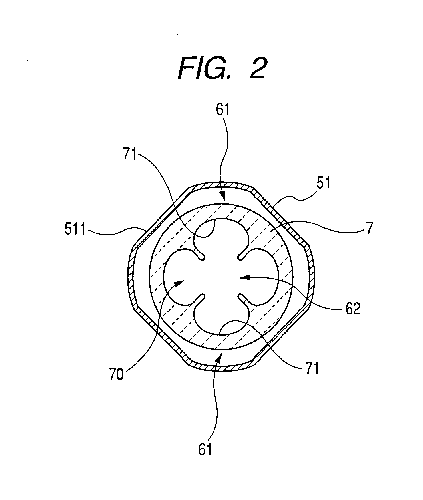
[0038] The air cover 5 is made up of a large-diameter port...


PUM

PropertyMeasurementUnit
areaaaaaaaaaaa
lengthaaaaaaaaaa
lengthaaaaaaaaaa

Abstract

A gas sensor includes a heater, leads connecting electrically with terminals of the heater, and a porcelain insulator surrounding the terminals of the heater within an air cover. The gas sensor also includes a recess formed in an end of the porcelain insulator to define a clearance between itself and an inner wall of the air cover. A gas flow path is defined to extend from an inner chamber of the air cover to a ventilator through a clearance between an outer periphery of the porcelain insulator and an inner periphery of the air cover and the recess to lead the gas having entered the inner chamber outside the sensor, thereby minimizing the entrance of the gas into the porcelain insulator to avoid the exposure of the terminals to the gas. This avoids the corrosion of the terminals with the gas to ensure the mechanical durability of the gas sensor.

Description

CROSS REFERENCE TO RELATED DOCUMENT [0001] The present application claims the benefit of Japanese Patent Application No. 2006-77875 filed on Mar. 21, 2006, the disclosure of which is totally incorporated herein by reference. BACKGROUND OF THE INVENTION [0002] 1. Technical Field of the Invention [0003] The present invention relates generally to a gas sensor which is installed, for example, in an exhaust system of automotive internal combustion engines to measure a specified component of exhaust emissions, and more particularly to an improved structure of such a gas sensor which is designed to has enhanced mechanical durability. [0004] 2. Background Art [0005] Japanese Patent First Publication No. 2001-330584 discloses a gas sensor to be installed in an exhaust pipe of automotive internal combustion engines to measure the concentration of a preselected gas contained in exhaust emissions from the engine. FIG. 12 shows such a type of gas sensor 9. [0006] The gas sensor 9 consists essent...

Claims


Application Information

Patent Timeline
Patent Type & Authority Applications(United States)
IPC IPC(8): G01N27/00G01M15/10
CPCG01N27/4077G01M15/102
Inventor NODA, HIROFUMIYOKOYAMA, TAIJI
Owner DENSO CORP
Why Eureka
Try Eureka