Diverted flow thrust bearing

a thrust bearing and flow technology, applied in the direction of sliding contact bearings, crankshafts, mechanical equipment, etc., can solve the problems of reducing the thrust load capacity of the above-described hydrodynamic thrust bearing, affecting the service life of the turbocharger, and reducing the thrust load capacity. , to achieve the effect of reducing the temperature of the oil film, reducing the amount of oil mixed, and increasing the thrust load capacity of the bearing

Inactive Publication Date: 2003-02-27
GARRETT TRANSPORATION I INC
View PDF9 Cites 6 Cited by
  • Summary
  • Abstract
  • Description
  • Claims
  • Application Information

AI Technical Summary

Benefits of technology

0012] In a preferred embodiment, the thrust pads comprise a series arrangement of three differently configured land sections. Configured in this manner, oil is provided onto the series of land sections by the oil supply groove and is collected after passing over the series of land s

Problems solved by technology

Thus, rotary action of the turbine also causes the air compressor to spin within a compressor housing of the turbocharger that is separate from the exhaust housing.
Thus, the hot oil exiting one pad exits the load-bearing surface via a groove that is also used to provide cool supply oil to an adjacent pad section, thereby adversely impacting the ability of such thrust bearing design to provide a desired degree of cooled oil to the load-bearing surface sections.
It has been discovered that the above-described hy

Method used


Image

  • Diverted flow thrust bearing
  • Diverted flow thrust bearing
  • Diverted flow thrust bearing

Examples


Embodiment Construction

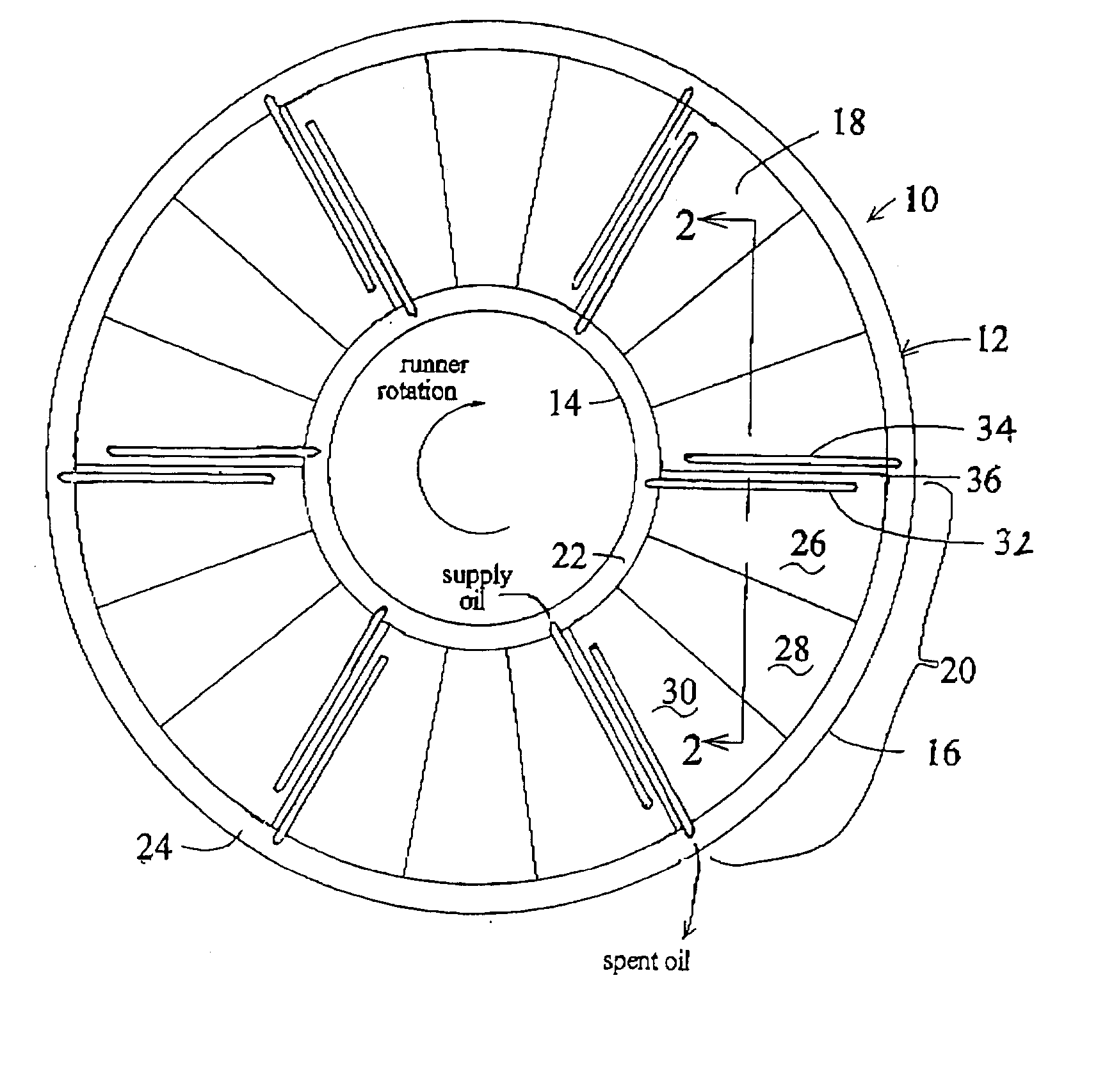
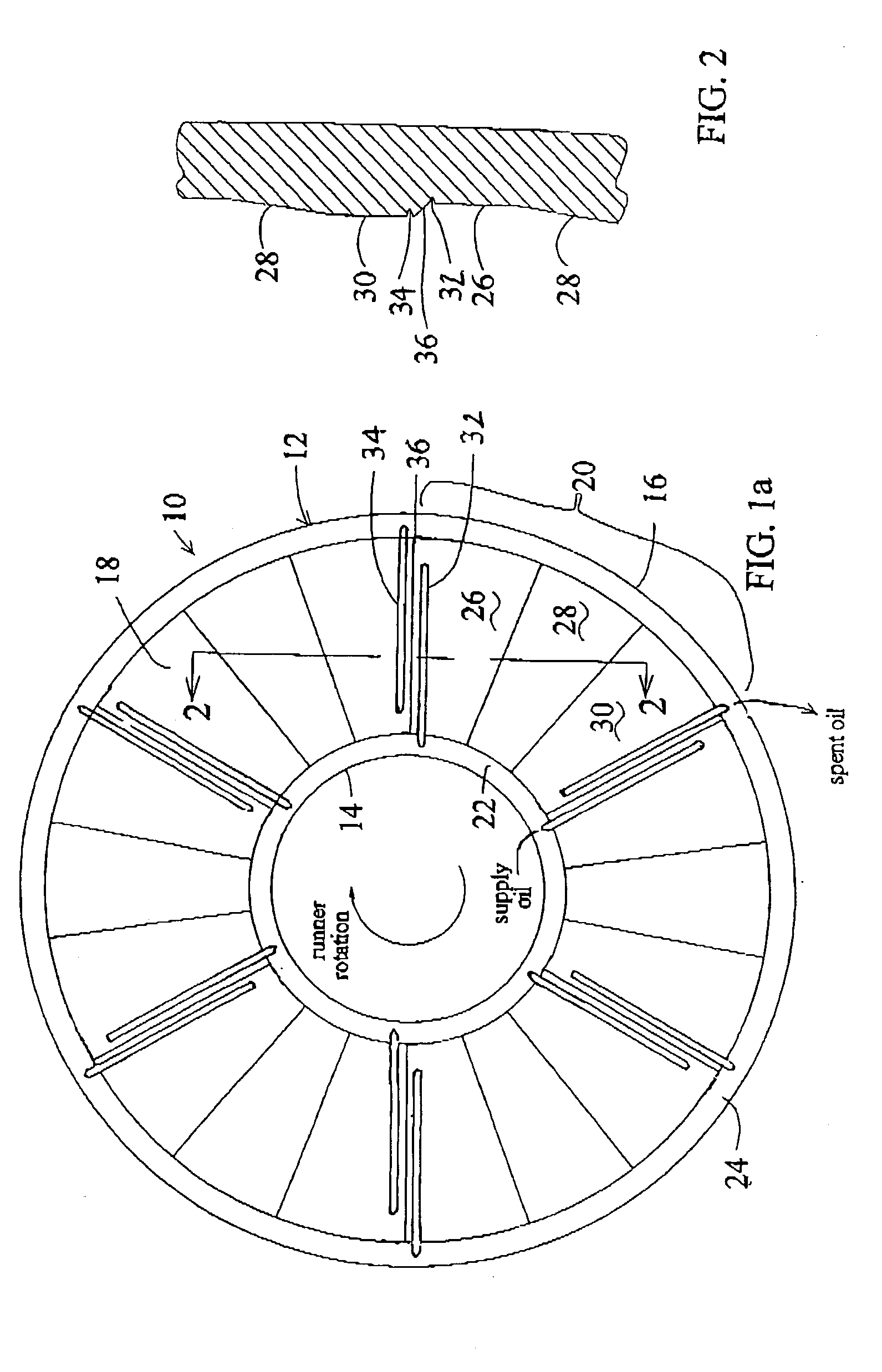
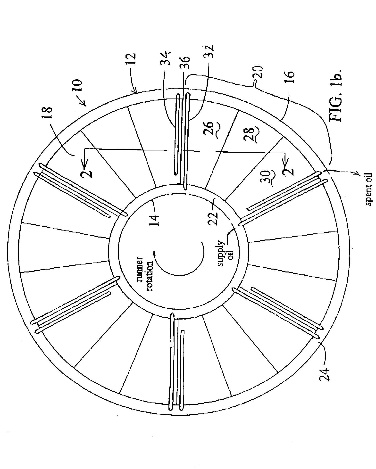
[0017] Referring to FIG. 1a, a hydrodynamic thrust bearing 10 of this invention has an annular body 12 comprising an inside diameter 14 and an outside diameter 16. The inside diameter is sized to accommodate placement of a turbine shaft (not shown), or alternatively a shaft bearing member (not shown), therein. The bearing includes an axially-directed face 18 that is designed to be positioned adjacent a turbocharger shaft member bearing surface (not shown) to control the extent of axial turbine shaft displacement within the housing. It is to be understood that thrust bearings of this invention can have one or both axially-directed load bearing surfaces configured in the manner described below.

[0018] The axially-directed load bearing face 18 comprises a repeating serial arrangement of three land sections 20, wherein each serial arrangement defines a thrust bearing thrust pad. An oil supply channel 22 is disposed along the bearing inside diameter along the axially-directed face 18, and...


PUM


Abstract

A hydrodynamic thrust bearing of this invention comprises a body having a load-bearing surface comprising an oil supply channel and an oil return channel positioned along respective inside and outside body diameters. A number of thrust pads are positioned along the surface that each include an oil supply groove, positioned adjacent a leading edge/upstream portion of each thrust pad and extending radially a distance from the oil supply channel, and an oil return groove, positioned adjacent a trailing edge/downstream portion of each thrust pad and extending radially a distance from the oil return channel. The oil supply grooves are separate from the oil return grooves, and the thrust pads each comprise a series arrangement of three differently configured land or pad sections. Configured in this manner, oil is provided onto the series of land sections by the oil supply groove and is collected after passing over the series of land sections by the separate oil collection groove. The use of separate oil supply and collection grooves acts to minimize mixing, of input oil with the heated return oil, thereby reducing oil film temperature and increasing bearing thrust load capacity.

Description

[0001] This patent application is a continuation-in-part of U.S. patent application Ser. No. 09 / 874,808 filed on Jun. 5, 2001.FIELD OF THE INVENTION[0002] This invention relates generally to the field of turbochargers and, more particularly, to a turbine shaft thrust bearing having separate oil inlet and oil outlet paths across a bearing axial surface, thereby providing improved bearing thrust load capacity and reduced oil film temperature.BACKGROUND OF THE INVENTION[0003] Turbochargers for gasoline and diesel internal combustion engines are devices known in the art that are used for pressurizing or boosting the intake air stream, routed to a combustion chamber of the engine, by using the heat and volumetric flow of exhaust gas exiting the engine. Specifically, the exhaust gas exiting the engine is routed into a turbine housing of a turbocharger in a manner that causes an exhaust gas-driven turbine to spin within the housing. The exhaust gas-driven turbine is mounted onto one end of...

Claims


Application Information

Patent Timeline
IPC IPC(8): F16C17/04F16C33/10
CPCF16C33/106F16C17/047F16C2360/24F16C33/1075
Inventor AGUILAR, SCOTT GROVER
Owner GARRETT TRANSPORATION I INC
Why Eureka
Try Eureka