Folding Type Portable Wireless Unit

a portable wireless unit and mobile radio technology, applied in the field of small folding mobile radio devices, can solve the problems of deterioration of the characteristics of the case when opened, spoilage of the antenna, and disturbance of the reduction in the size and thickness of the mobile radio device, and achieve the effect of high antenna performance and suitable for miniaturization

Inactive Publication Date: 2008-12-04
PANASONIC CORP
View PDF4 Cites 30 Cited by
  • Summary
  • Abstract
  • Description
  • Claims
  • Application Information

AI Technical Summary

Benefits of technology

[0028]According to the present invention, the folding mobile radio device that is able to show the high antenna performance by a single antenna in open and close states not to take up a large space and is suitable for miniaturization can be provided.

Problems solved by technology

However, according to the above structure, the projection portion of the antenna spoils an external appearance as the mobile radio device.
Also, a whip antenna needs a housing space in the case and disturbs a reduction in size and thickness of the mobile radio device.
In this case, since there is a limit to a length as the built-in monopole antenna, an electric coupling with the upper case is weak when the case is opened, and thus the characteristics when the case is opened are deteriorated.
Also, when the inverted F-type antenna is provided to the upper case, a height from the substrate in the upper case must be kept to ensure the characteristics and also an area of the plate-like antenna must be widened, which causes an obstruction to a reduction in size and thickness of the mobile radio device.
However, this antenna configuration acts as an ideal λ / 2 dipole antenna when the case is opened, nevertheless the current flows are cancelled mutually when the case is closed and this antenna configuration cannot act as the antenna in theory.
As a result, another antenna that can operate when the case is closed is needed and thus its circuit configuration becomes complicated.
The above problems are not restricted to the folding cellular phone and will arise in the normal folding mobile radio device.

Method used


Image

  • Folding Type Portable Wireless Unit
  • Folding Type Portable Wireless Unit
  • Folding Type Portable Wireless Unit

Examples


first embodiment

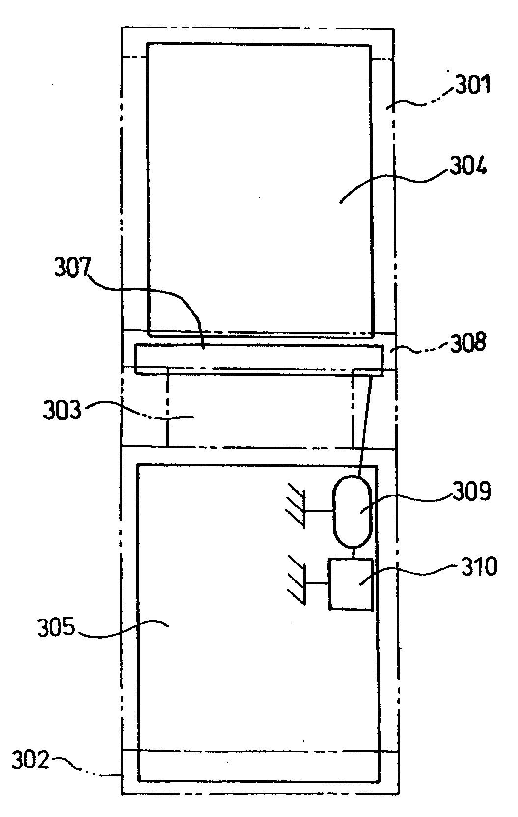
[0085]FIG. 3 shows a folding mobile radio device according to a first embodiment of the present invention, and shows an example where the present invention is applied to a folding cellular phone. In this folding cellular phone, an upper case 301 constituting a first case and a lower case 302 constituting a second case are joined by a hinge portion 303 constituting a joint portion. The folding cellular phone takes two states of an open state and a close state because the upper and lower cases are turned on the hinge portion 303.

[0086]A liquid crystal display portion (LCD) 306, a receiver portion (speaker) (not shown), and the like are provided to the upper case 301. Also, an upper substrate (first substrate) 304, and the like are arranged in the inside, and a plate-like conductor element 308 that is connected to the upper substrate 304 and constitutes a conductor element is arranged on the back side. The plate-like conductor element 308 is arranged on one end portion of the upper cas...

second embodiment

[0096]FIG. 7 is a view showing a folding cellular phone according to a second embodiment of the present invention. In FIG. 7, the same reference symbols as those in FIG. 3 indicate the same constituent elements, and their detailed explanation will be omitted herein.

[0097]The folding cellular phone of the present embodiment shown in FIG. 7 is similar to the structure in FIG. 3 in that the upper case 301 and the lower case 302 are joined by the hinge portion 303 and also the feeding metal plate 307 is arranged on one end portion of the lower case 302 near the hinge portion 303. Also, the feeding metal plate 307 has a pin-shaped contact portion 703 and this contact portion 703 is projected from the lower case 302 to constitute an exposed structure. Also, a ground pin 701 connected to the upper substrate 304 is provided on the back side of the upper case 301, and is exposed from the lower case 302 through a through hole 704 formed in the upper case 301. According to this structure, the ...

third embodiment

[0100]FIG. 8 and FIG. 9 are views showing a folding cellular phone according to a third embodiment of the present invention. FIG. 8(a) is a back view in its open state, FIG. 8(b) is a side view in its open state, and FIG. 9 is a side view in its close state. In FIG. 8 and FIG. 9, the same reference symbols as those in FIG. 3 indicate the same constituent elements, and their detailed explanation will be omitted herein. Here, explanation will be made under the assumption that an operating frequency of the antenna is in a 2 GHz band.

[0101]As shown in FIG. 8 and FIG. 9, in the folding cellular phone according to the present embodiment, a conductor element 801, the upper substrate 304, the liquid crystal display portion 306, and a receiver portion (speaker) 803 are provided to the upper case 301. Also, a feeding element 802, the lower substrate 305, the matching circuit and the radio circuit (both not shown), and a transmitter portion (microphone) 804 are provided to the lower case 302.

[...


PUM


Abstract

In a folding type portable wireless unit, gain deteriorates sharply upon closure, in the case where an upper case is oscillated directly at the time of opening and used as an antenna in order to attain a wide band and a high gain. The folding type portable wireless unit comprises a first case, a second case, a coupling part for coupling the first and second cases to be opened/closed, a conductor element arranged in the first case, and a power supply element arranged in the second case. In the open state brought by the coupling part, the conductor element and the power supply element approach closely to each other and can be coupled electromagnetically at the time of power supply. In the closed state brought by the coupling part, the conductor element and the power supply element separate from each other as compared with the open state and they are not coupled electromagnetically at the time of power supply.

Description

TECHNICAL FIELD[0001]The present invention relates to a small-sized folding mobile radio device having a high antenna performance.BACKGROUND ART[0002]Recently, the cellular phone as one type of the mobile radio device is spreading widely, and various types of the cellular phone have been developed. Among them, the folding compact type whose upper and lower cases are folded to enhance a portability when the cellular phone is not used is widely used. It is important that, since cellular phone is constructed to change its form according to the use situation, the antenna performance should be ensured in respective states. Also, a miniaturization and a multifunction is proceeding in the folding mobile radio device, and employment of the built-in antenna is proceeding as one of multifunctional tendencies to improve a design property.[0003]Normally, as a means for achieving a good antenna performance in the folding cellular phone in both its open state and its close state, three examples w...

Claims


Application Information

Patent Timeline
Patent Type & Authority Applications(United States)
IPC IPC(8): H04Q1/24H04M1/02
CPCH01Q1/243H01Q9/285H01Q9/42H04M1/0216
Inventor UEJIMA, HIROYUKIISODA, YUTAKAMASHIMA, NOBUHARUHIRAI, MASAYOSHIIWAI, NOBUHIROSAITOH, YUTAKAMAEDA, KENICHI
Owner PANASONIC CORP
Why Eureka
Try Eureka