Ankle Foot Orthosis Device

a technology for ankles and orthoses, applied in the field of orthotics, can solve the problems of cumbersome use of above-referenced devices, early joint degeneration, and foot slapping the ground,

Inactive Publication Date: 2008-12-04
YAAD ADVANCED ORTHOPEDICS
View PDF10 Cites 30 Cited by
  • Summary
  • Abstract
  • Description
  • Claims
  • Application Information

AI Technical Summary

Benefits of technology

[0057]In embodiments of the invention, the method may include, for example, the act of mechanically coupling the lower-leg-holder to the elongate member such that a curved part of the support-brace substantially points in a direction that corresponds to the patient's direction of gait, thereby enabling the patient to rest his / her lower leg that corresponds to the drop foot against the inner surface of the support-brace.

Problems solved by technology

Because the patient suffering from drop foot condition lacks full control of his foot, difficulties arise when walking such as dragging the toe when swinging the leg forward or slapping the foot when the heel strikes the ground.
If left uncorrected, knee crouch can lead to early joint degeneration.
Due to the conforming nature of the brace it is inconspicuous when worn, for the upper portion of the brace is situated within the confines of the trouser leg of a user, and the lower portion of the brace within a shoe.
However, with no lateral stability, the foot may still slap the ground.
However, the above-referenced devices may be cumbersome to use and may not be useful in helping clear the foot from the floor, since they are inefficient in compensating the energy loss caused in foot suffering from drop foot condition.
Furthermore, the devices are not adjustable to the different needs of different patients.

Method used


Image

  • Ankle Foot Orthosis Device
  • Ankle Foot Orthosis Device
  • Ankle Foot Orthosis Device

Examples


Embodiment Construction

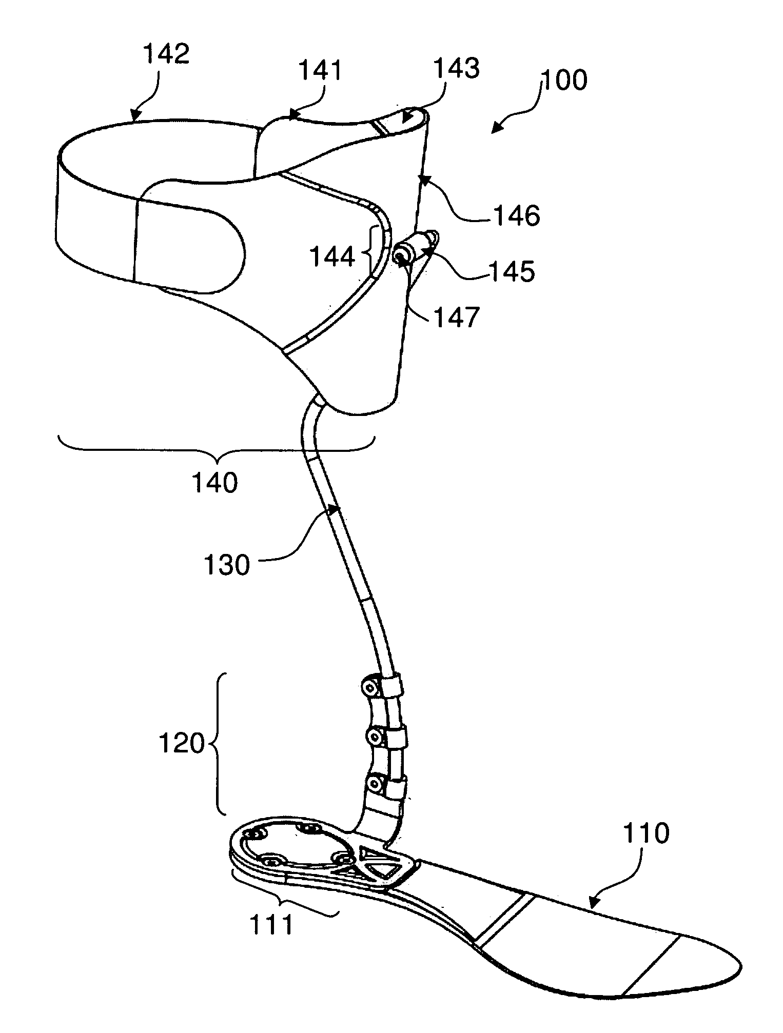
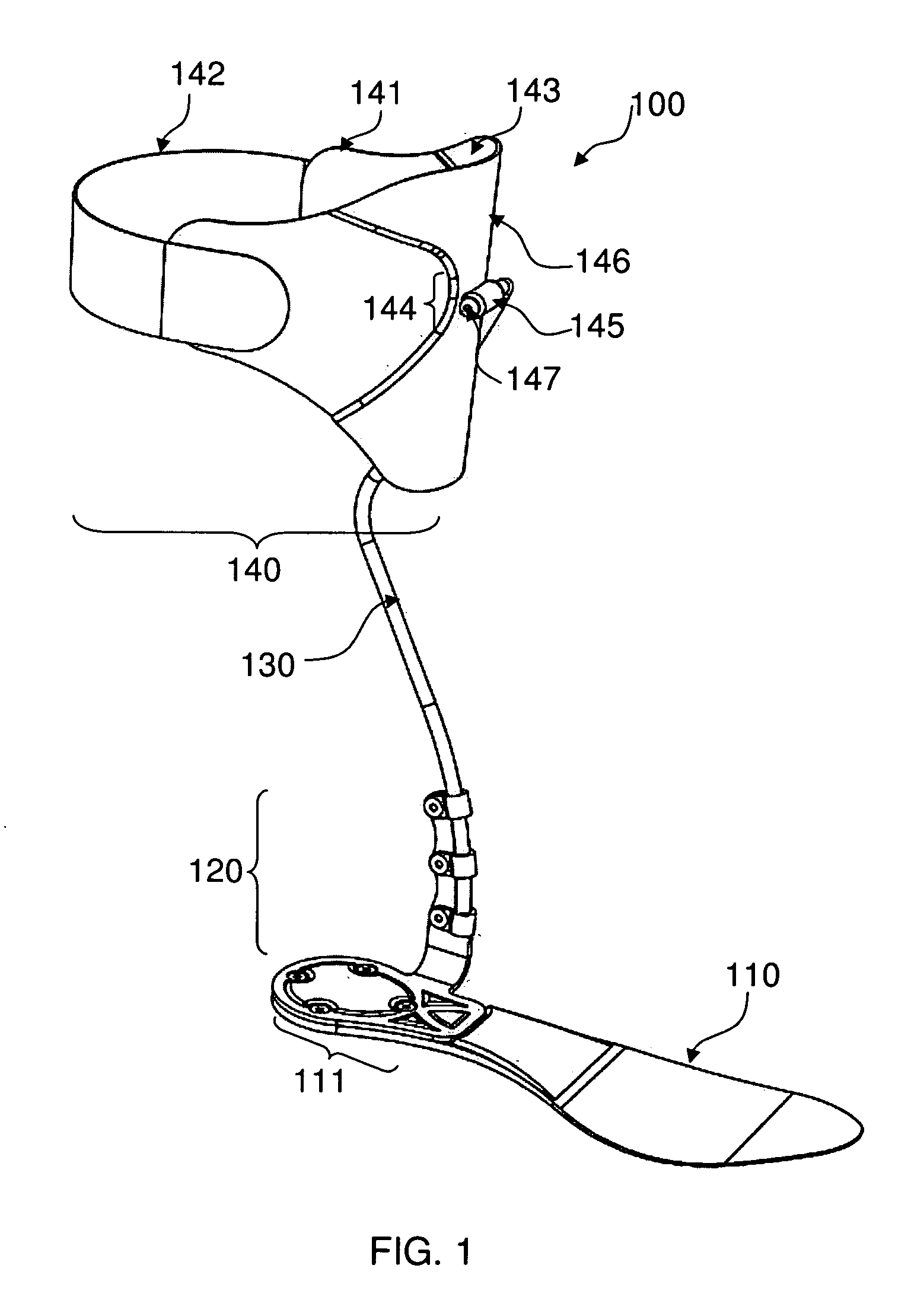
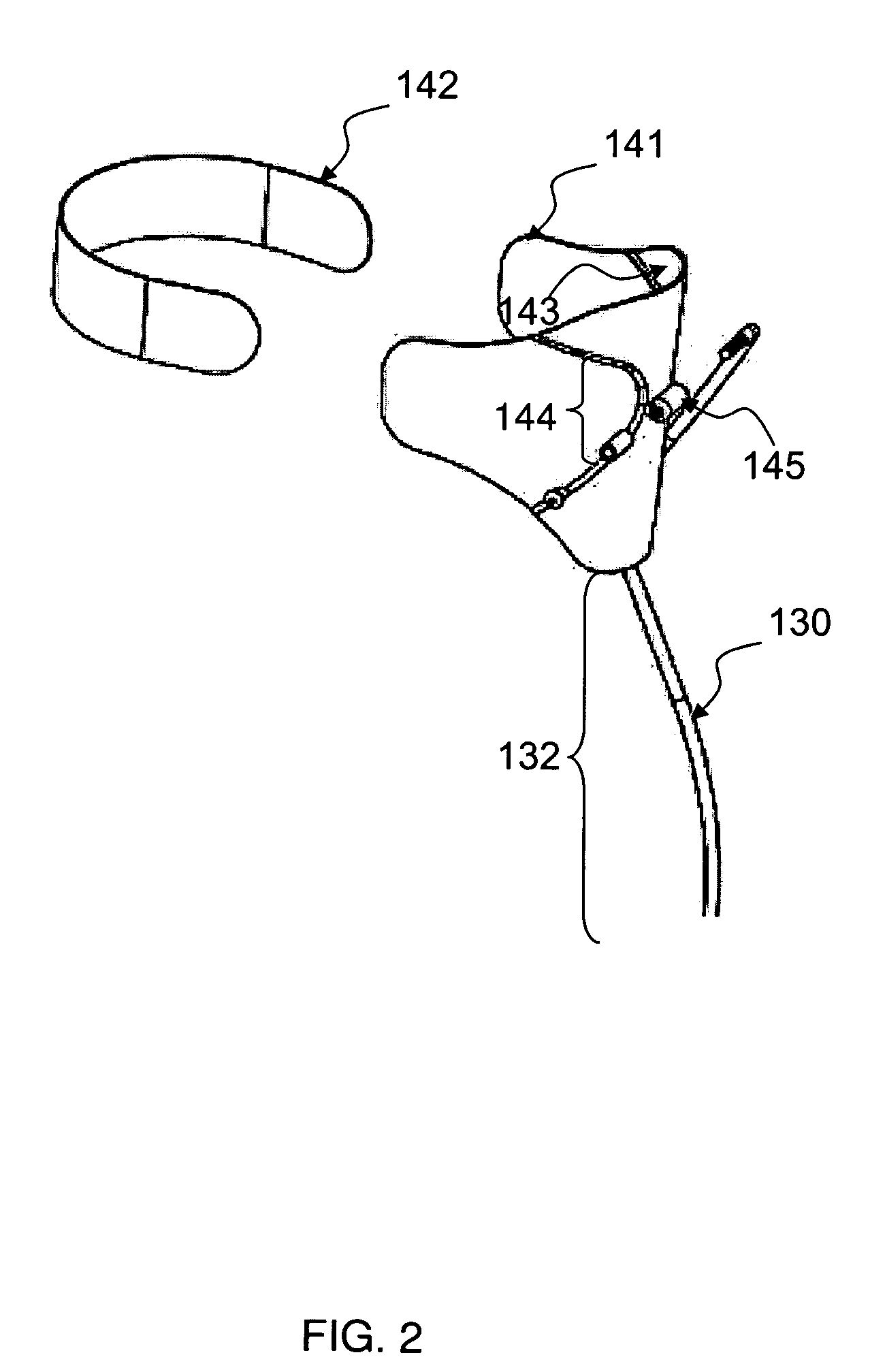
[0072]The present invention relates to an ankle foot orthosis (AFO) device. According to some embodiments of the invention, the AFO device includes a flexible foot-support to which a flexible elongate member is substantially fixedly coupled. The AFO device further includes a lower-leg-holder that is mechanically coupled to an upper part of the elongate member. The AFO device is designed in a manner such that when it is suitably engaged with a patient's drop foot, the AFO device stores potential energy during, for example, the transition from the mid-stance to the terminal-stance phase of the patient's gait cycle. At least some of the stored potential energy may be released during the subsequent toe-off phase of the patient's gait cycle, whereby the released potential energy may at least partially compensate for, e.g., the muscle weakness in the drop foot. Consequently, the AFO device may cause ground clearance of the patient's drop foot during at least some of the gait cycle's swing...


PUM


Abstract

The present invention discloses an ankle foot orthosis device that is adjustable to a patient's drop foot. The device may include, inter alia, a foot-support that is sized to fit into a corresponding patient's footwear; an elongate member that is mechanically coupled to the foot-support; and a lower leg holder that is coupled to the elongate member. The lower portion of the elongate member may extend from the foot-support's heel portion upwards and rearwards towards a corresponding lower leg's calf and may further extend forwardly towards the corresponding lower leg's shin. Forward tilting of the lower leg in the gait cycle causes the elongate member to bend forward, which in turn causes the development of potential energy in the device that may be released during the gait cycle's toe-off and swing phase, thereby compensating for the energy lost in the drop foot.

Description

FIELD OF INVENTION[0001]This invention relates generally to orthotic devices. More specifically, the present invention relates to orthotic devices that assist people suffering from drop foot condition.BACKGROUND OF THE INVENTION[0002]Glossary[0003]a) “ankle”—the joint between the lower leg and the foot[0004]b) “calf”—posterior portion of the lower leg[0005]c) “drop foot condition”—medical condition describing a patient's inability in pivoting a foot upward[0006]d) “drop foot”—the patient's foot suffering from the drop foot condition[0007]e) “extensors”—muscle that straightens a body part[0008]f) “foot”—the lower extremity of the lower leg below the ankle[0009]g) “heel bone”—the largest tarsal bone[0010]h) “knee”—joint in the middle of the leg[0011]i) “lower leg”—part of the leg between the knee and the foot[0012]j) “shin”—anterior part of the lower leg[0013]Drop foot condition, also known as steppage gait, is a medical condition that pertains to a deficit in pivoting the foot upward...

Claims


Application Information

Patent Timeline
Patent Type & Authority Applications(United States)
IPC IPC(8): A61F5/00
CPCA61F5/0111
Inventor SHLOMOVITZ, TAL
Owner YAAD ADVANCED ORTHOPEDICS
Why Eureka
Try Eureka